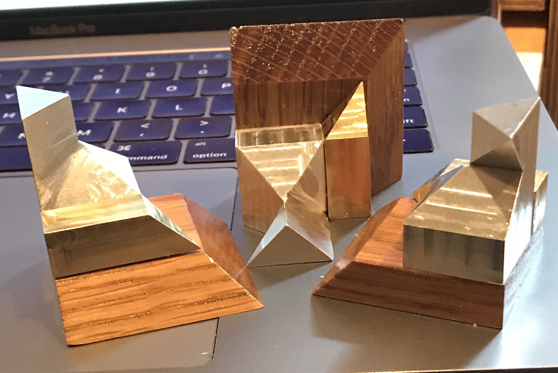
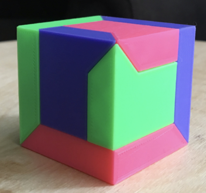
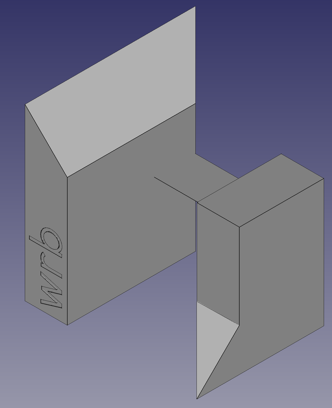
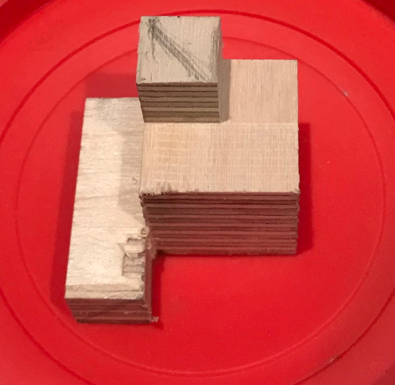
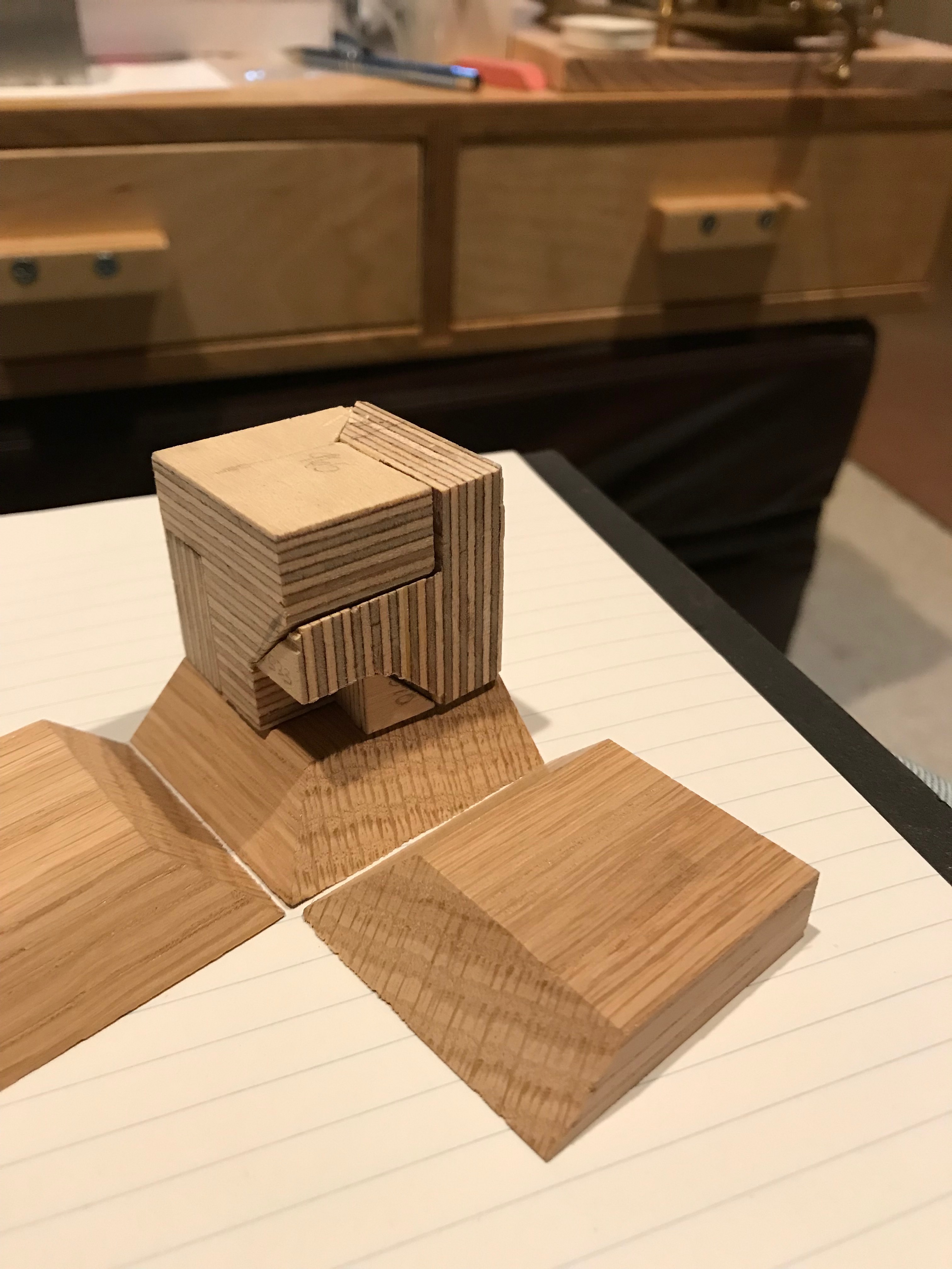
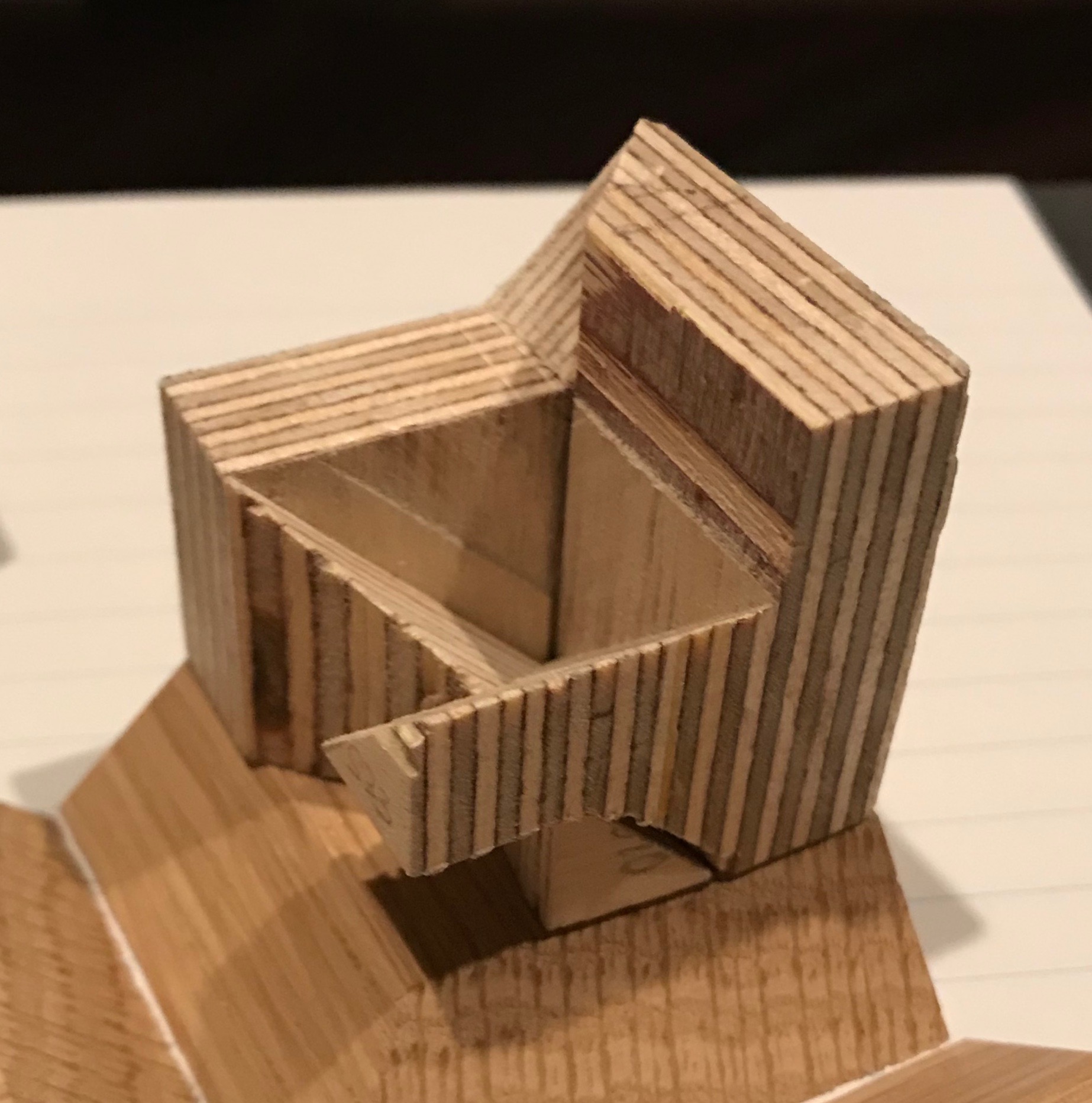
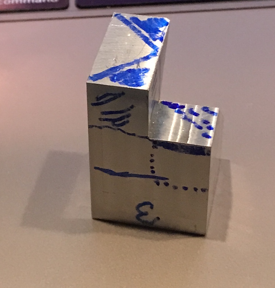
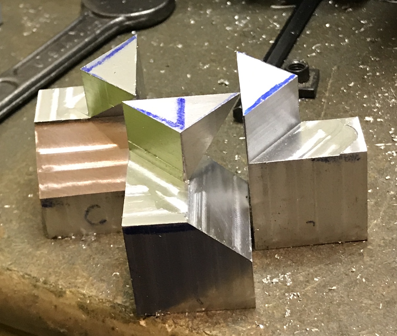
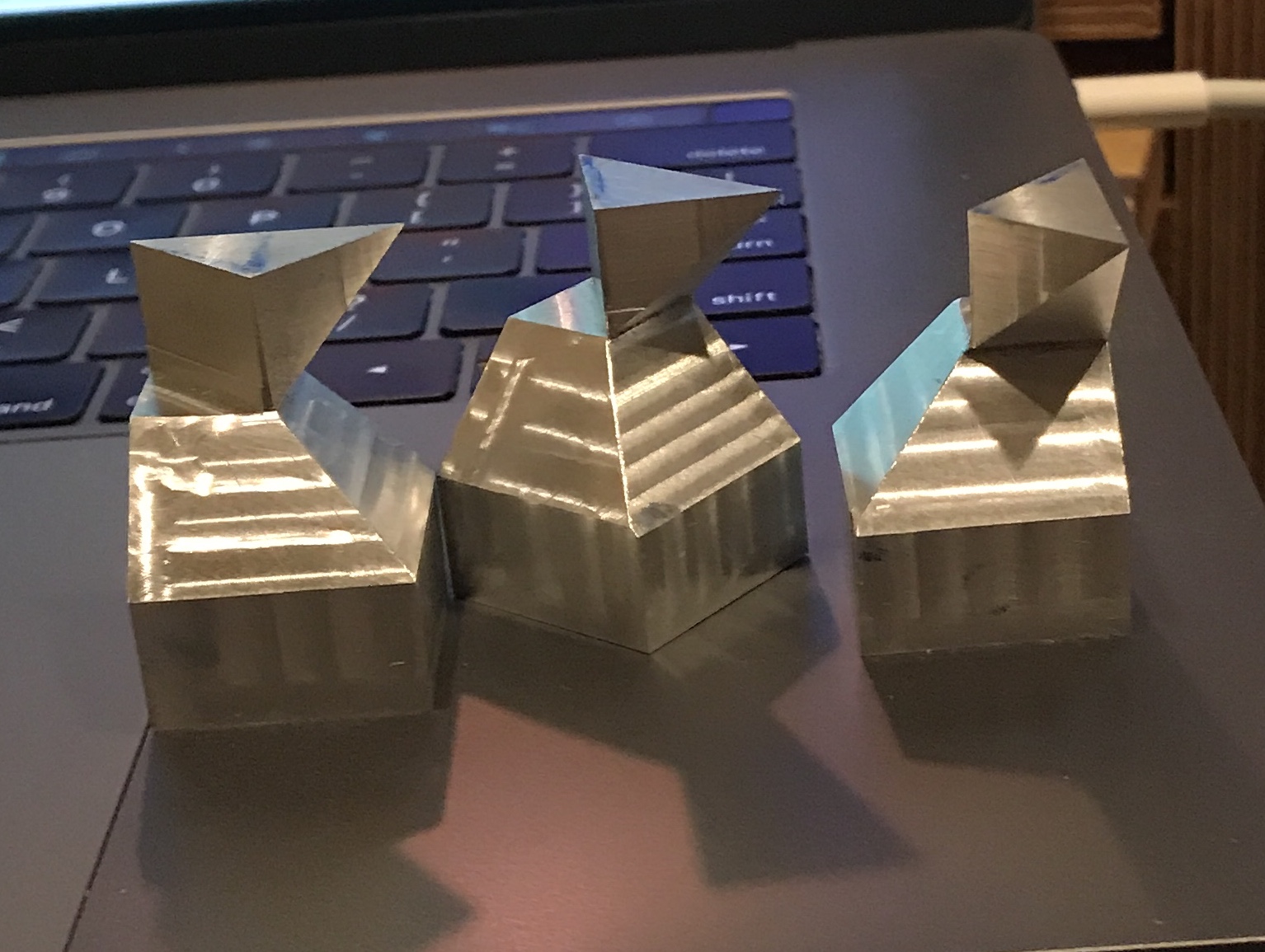
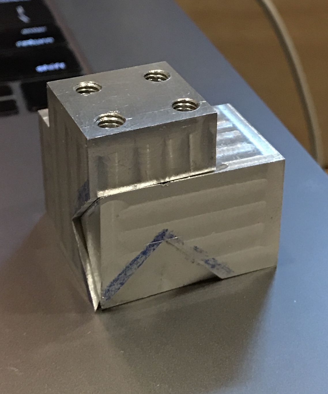
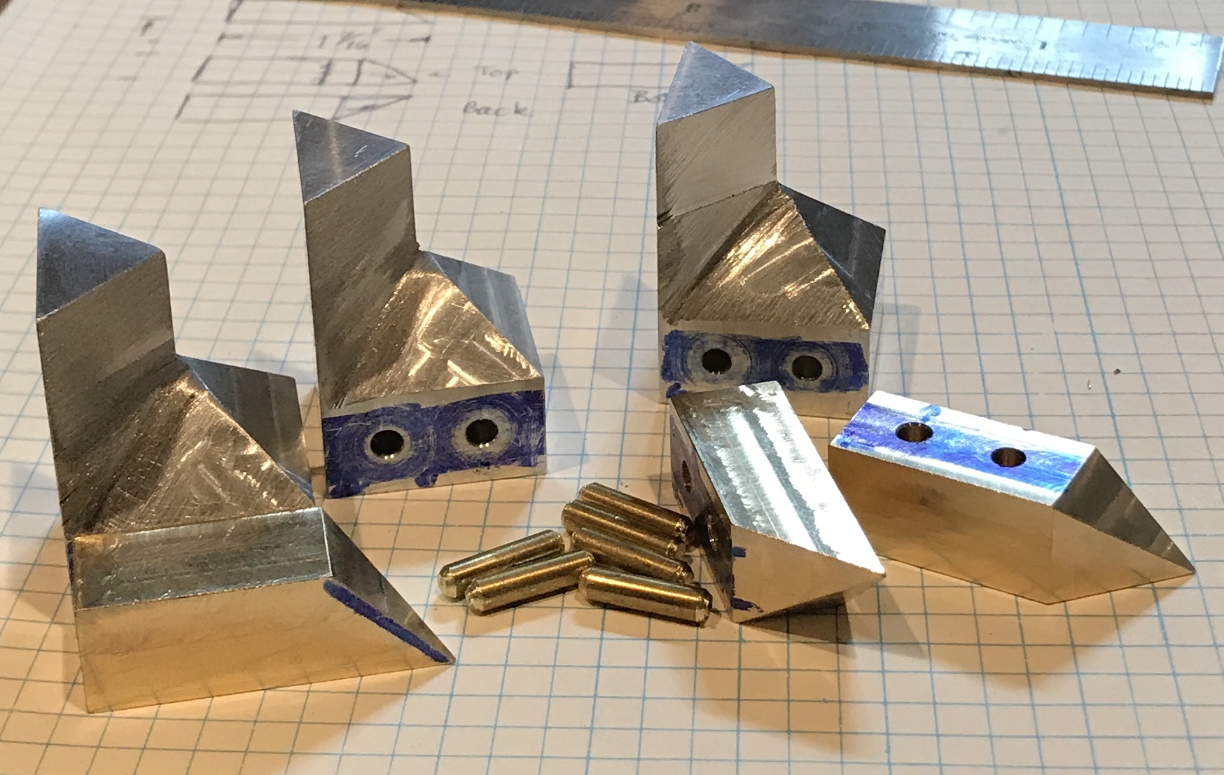
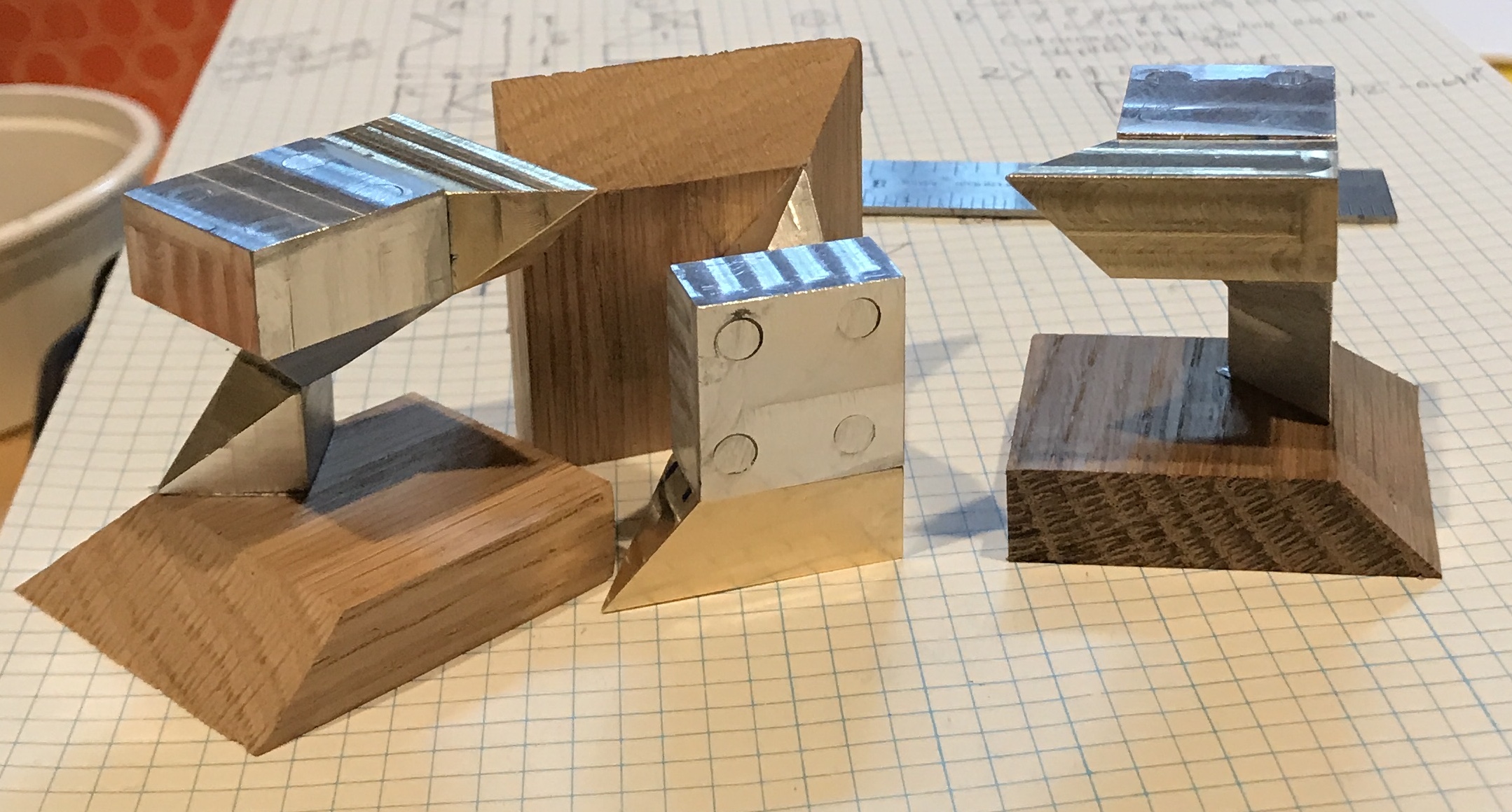
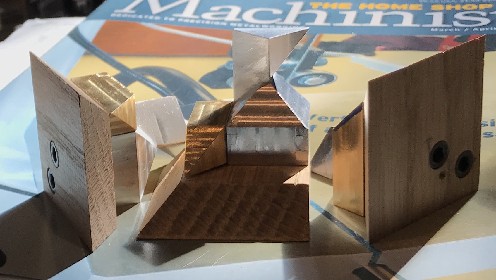
An interesting puzzle was seen on the internet by WildRoseBuilds. The example shown was 3D printed. It consists of a cube cut into three identical pieces that slide together in an interesting fashion. The puzzle included plans in FreeCAD format. All I have been able to do with the plan is view it from various angles in both orthographic and perspective views. The three identical parts would be easiest to make from two subunits. One is a simple square beveled on two adjacent sides at a 45° angle. (The backside green & blue and bottom red parts in the picture below.) The other subunit is significantly more complex. In fact it wasn't until three or four days of trying to understand its shape that I finally realized there was an almost hidden 45° angle in one place. The angle is on the bottom of the projection connecting the two subunits. This is seen in the third picture below.
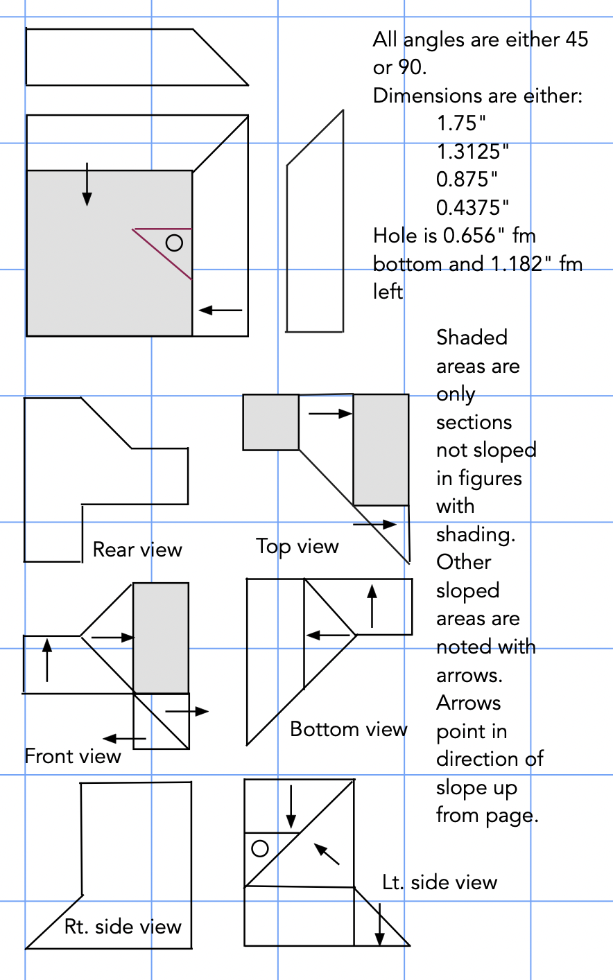
Metal was purchased, but due to the challenges of making this part the project began with a wooden prototype. The sizes of all dimensions were fractions of the overall cube size. A cube size of 1.75" has 1.3125", 0.875", and 0.4375" lengths for all of its various features. Angles are always 45°. A length of 1/2" thick wood was cut to 1.75" and then further cut into 1.75" squares. Two adjacent edges were cut at a 45° angle by tilting the milling table head. The thickness was then reduced to 0.435". (Slightly below stated thickness to make sure there was sliding room.)
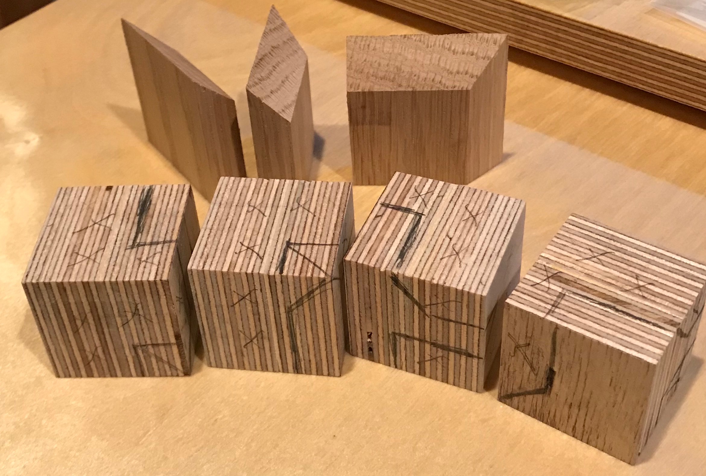
Baltic birch plywood (3/4" thick) was glued up and cut to produce four 1 3/8" cubes. These cubes were reduced to 1.310" cubes with the mill. The appropriate cutting plan was sketched on the faces of these cubes.
The first cube was mounted in the milling vise on parallels. The vise was indicated after aligning with the square. It was less 0.001" out of alignment! The top and side were 'found' with the end mill and the end mill was lowered 0.200". The end mill was moved sideways 0.100" and the first cut was taken down the side of the cube. Successive cuts were taken to fit the design. This was repeated on other faces until the shape was complete except for the four angled cuts. This milling was repeated with three more cubes. (One for just in case!)
The picture below has a mistake. The angle indicated on the top small cube should run perpendicular to that shown.
The next order of business is cutting the four angles on each block. With these cut the blocks should assemble into a cube.
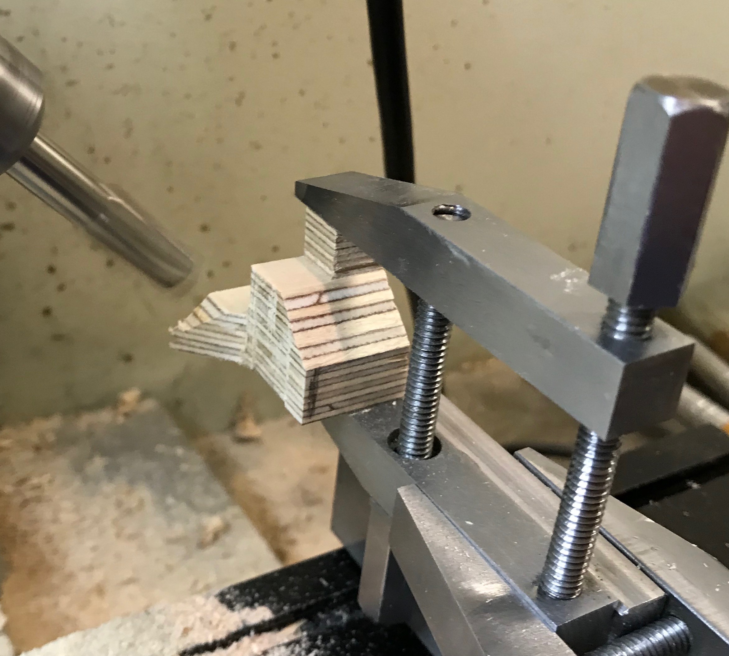
The extended corner that comes to a point was cut first. With the milling head set to 45° the block was clamped high on the angle plate with the aid of two machinist's clamps. Then the end mill could be touched off on the flat face and the angle milled. Rotating the part 90° allowed the adjacent side to be similarly milled.
The final angle had to be milled with the use of the angle plate. After doing this to all four blocks assembly was attempted. There are two errors in the blocks as milled. One is an error of commission. The angle on the part that attaches the two subparts together was milled the wrong way. The second is an error of omission. One of the two angles cut on the protruding point needs to be continued across the center of the part. So additional wooden cubes need to be remade for testing these new cuts. Additionally, a lot of thought needs to go into holding and milling in order to transfer the knowledge learned on the wooden parts to cutting the metal subassemblies.
Arrrgh! I thought I was done generating sawdust!! Of course, that is why I did a prototype in wood. I am wearing a dust mask, while milling these parts.
When milling the complex subpart, significant thought needs to go into the order of milling to maximize the surface being held in the vise or clamps. The hole should be drilled in the complex subpart immediately after squaring up the cube. Otherwise it will be challenging to find a good corner for measuring. Using a jig for drilling this hole and the mating hole in the other subpart will maximize accuracy.
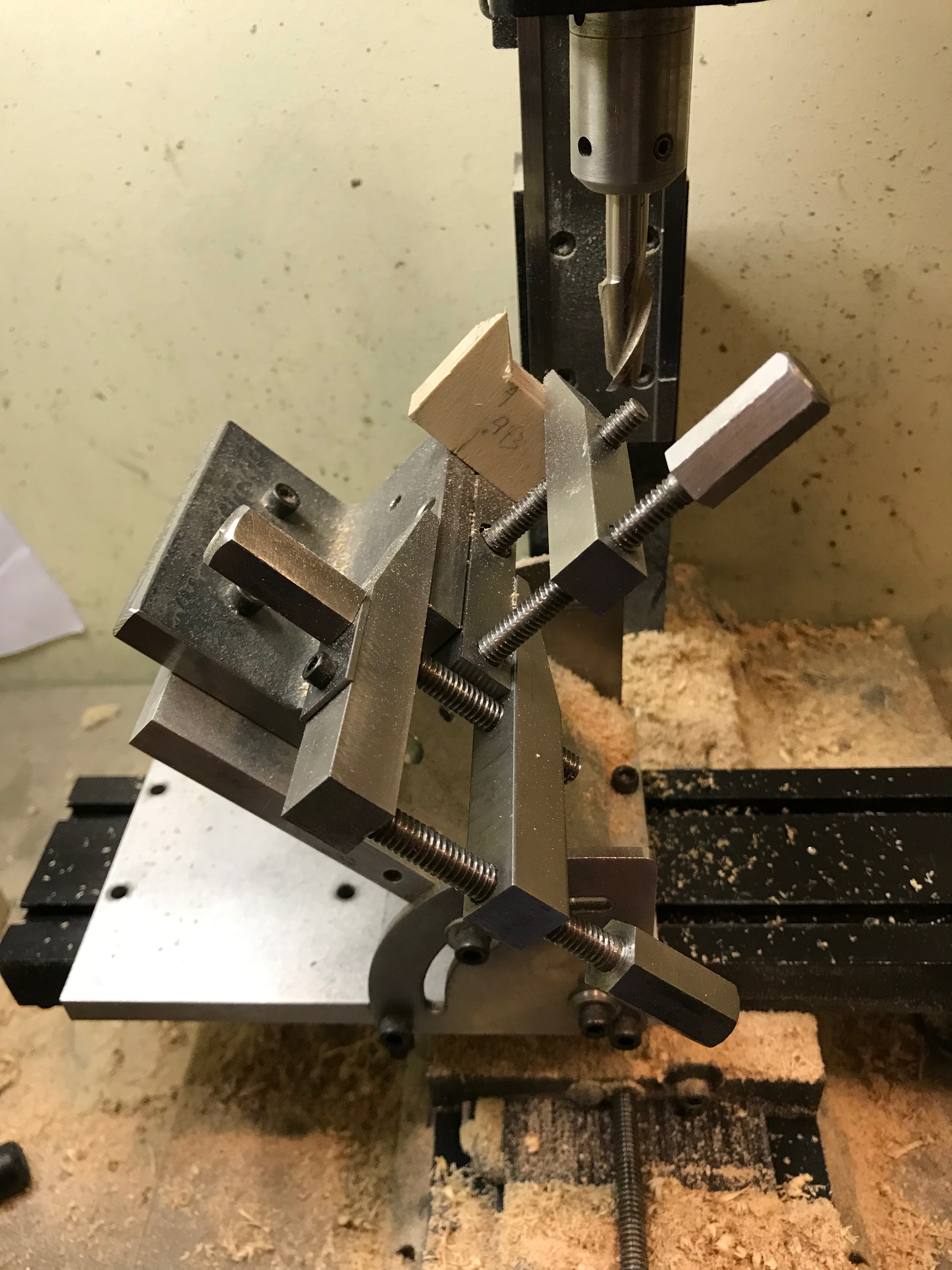
Three new 1 3/8" cubes were glued up and squared up to size. Three series of cuts gave blocks similar to that shown above on the red lid. Then two angled cuts were made with the block held in the vise. These two cuts are both from either side of the center projection down. (As seen from the block posed on the red lid above.) The angles on the two projections were cut next. The doubly cut projection was held in the clamps on the angle plate and the projection that attaches to the other part was held in clamps on the angle plate on the sine plate. (per the following photo)
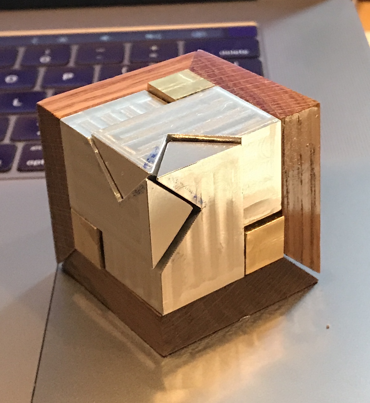
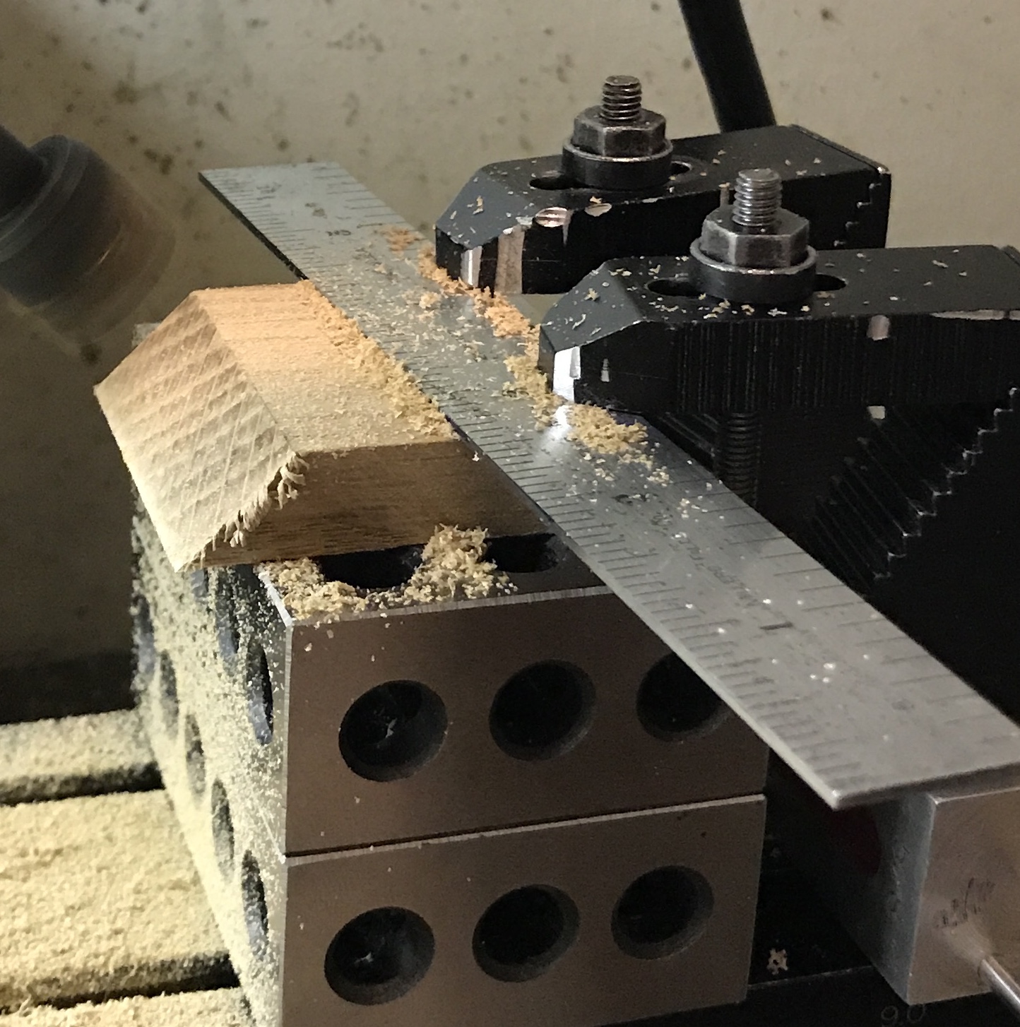
This leaves one final cut to make. This is an inside cut. It can be seen in the "Front" and "Bottom" orthographic views above or sketched on the wooden part in the photo below. The wood to be removed to the left of the frontmost pencil line needs to be cut back to the angle of the projection. The wood between the two lines must be cut back to a hidden line that runs from the top end of the rightmost line to the bottom end of the leftmost line. It may be possible to do the cuts with end mills in exactly that order. Setting up for the angles will require a holding fixture of some sort.
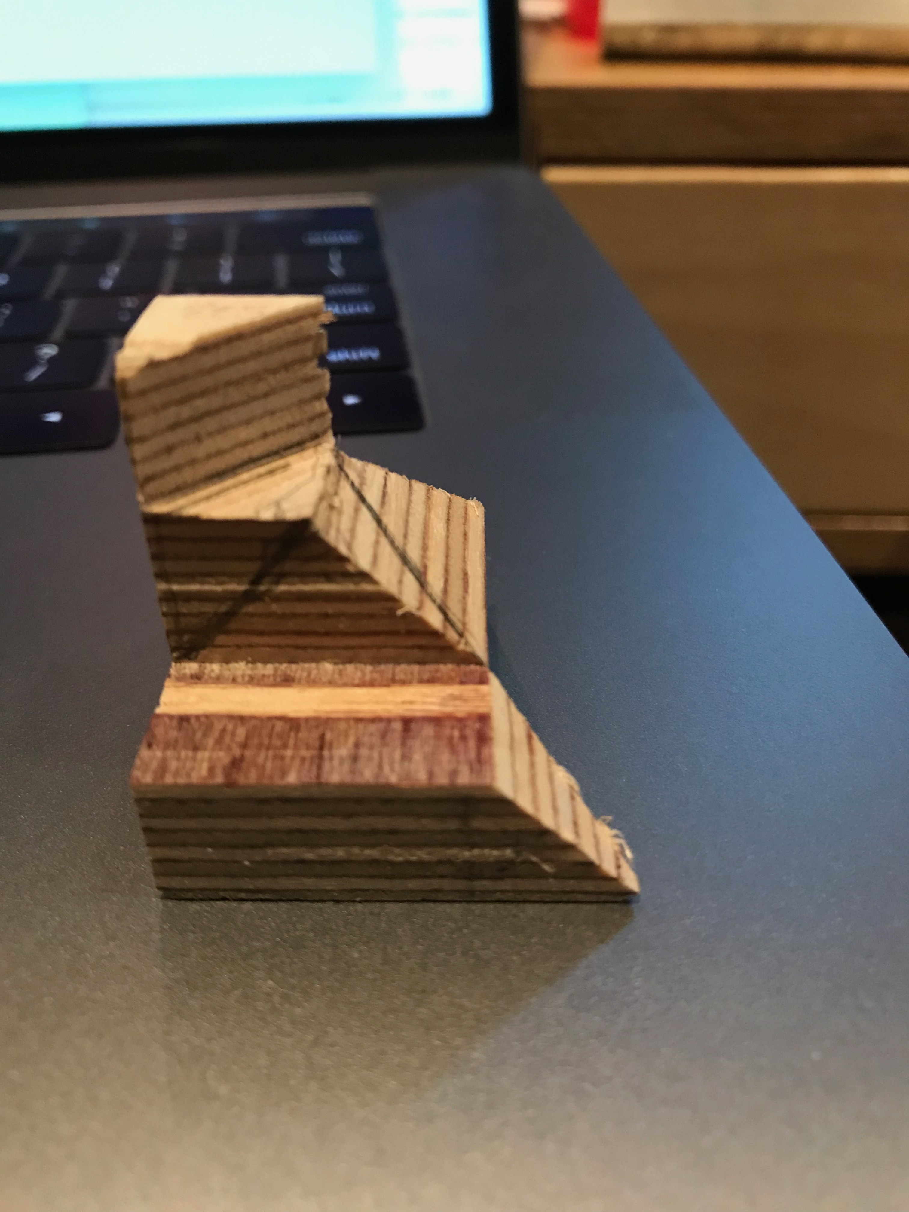
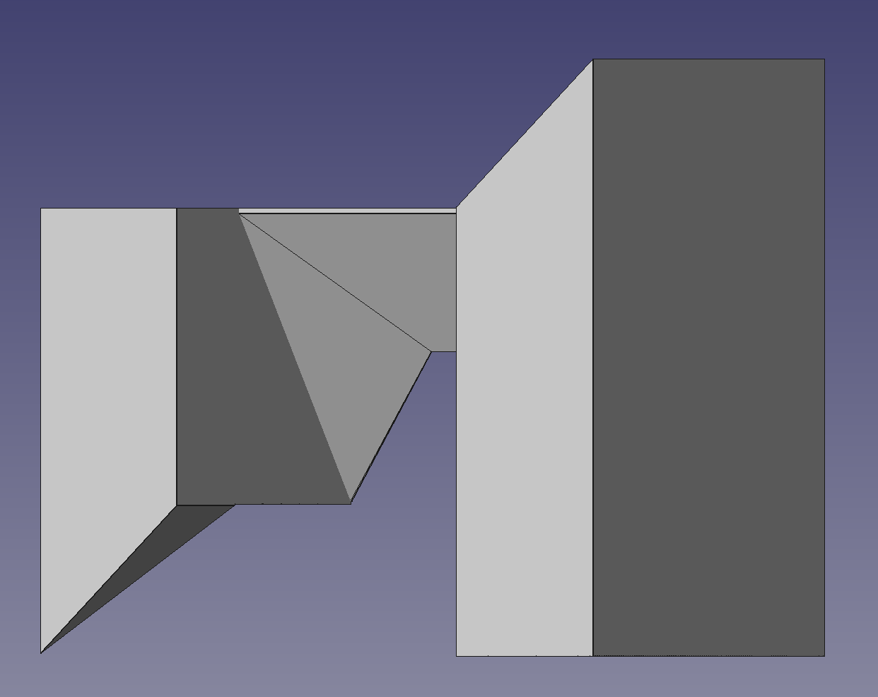
I can't believe how blind I have been! This inside cut is much simpler than I believed. Looking at the above picture simply take all of the volume with two lines and remove it. Down to the brown layer with the stripe and back to the back right corner. I had been fooled by a line, that I would have expected to be a change in angle in the FreeCad display. The picture below, halfway between bottom view and left side views, clearly shows the offending line.
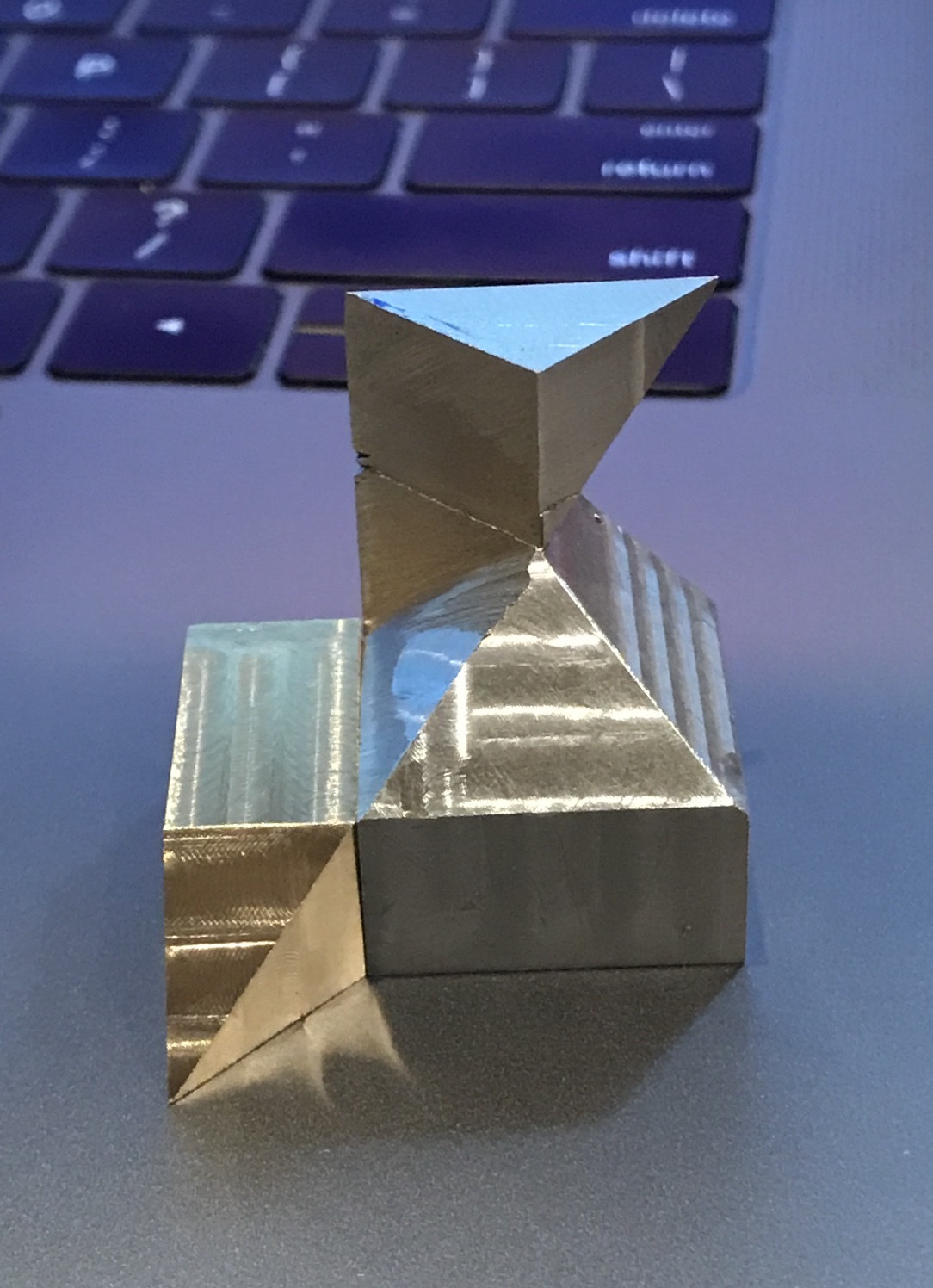
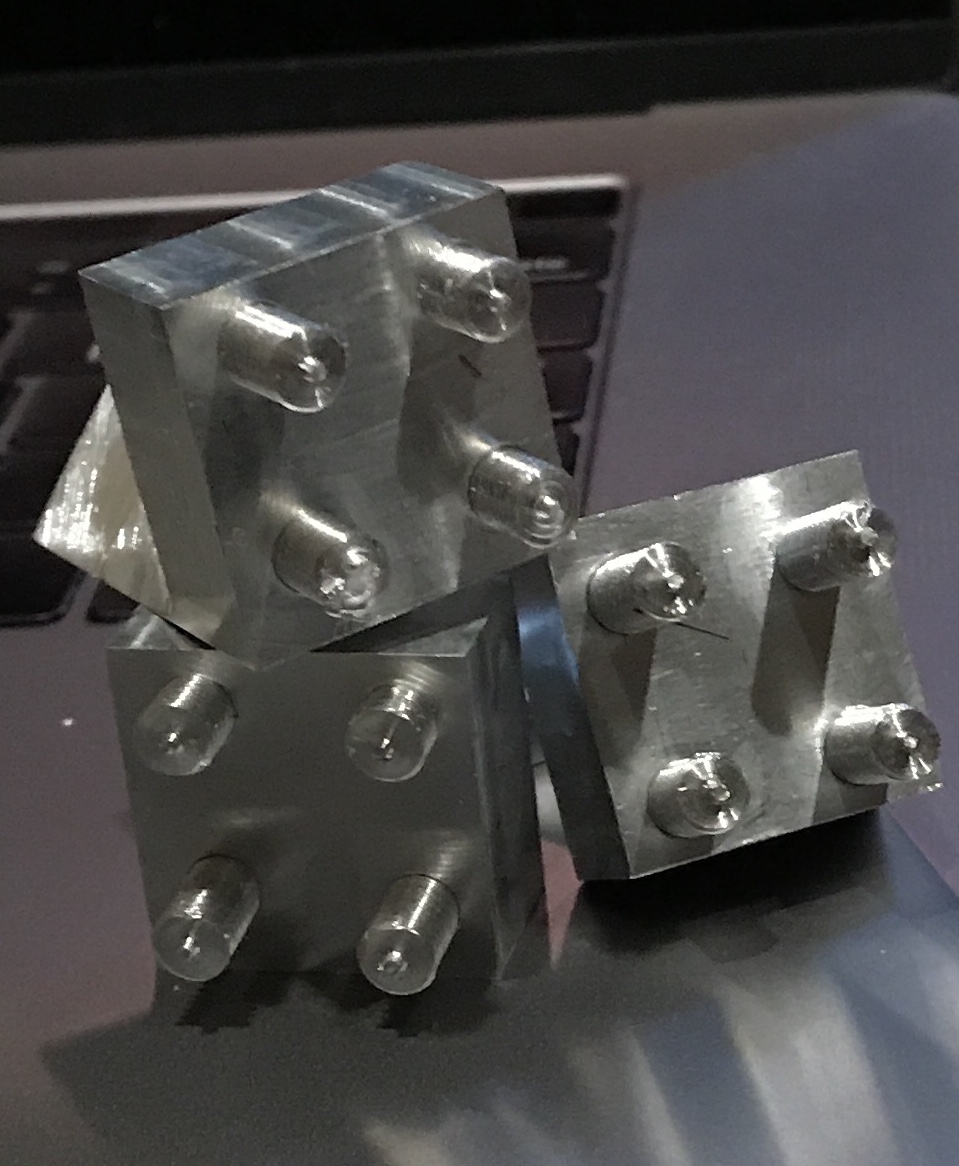
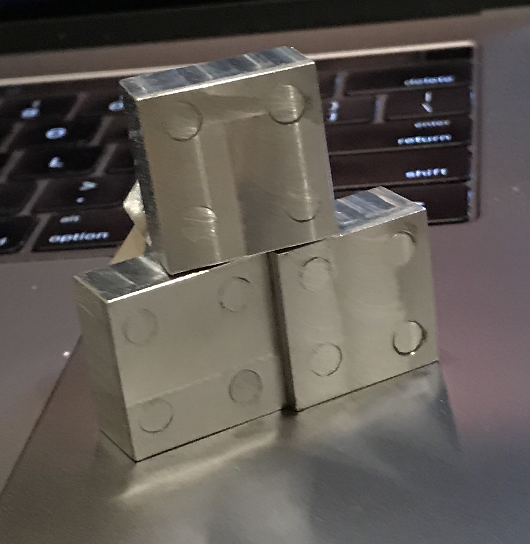
So let's mill it off and validate the truth of my new vision. Ah, the sweet taste of success. The three subparts fit reasonably well. Interestingly, there are two gaps in the the internal cube. The final assembly and partial disassemblies are shown below. The latter two highlight the 'holes' in the inner cube.
I am guessing that if I had cut off the marked part as originally planned there might not be a middle hole. Looking at these pieces in the partial assembly leads me to believe that they would also still slide past each other.
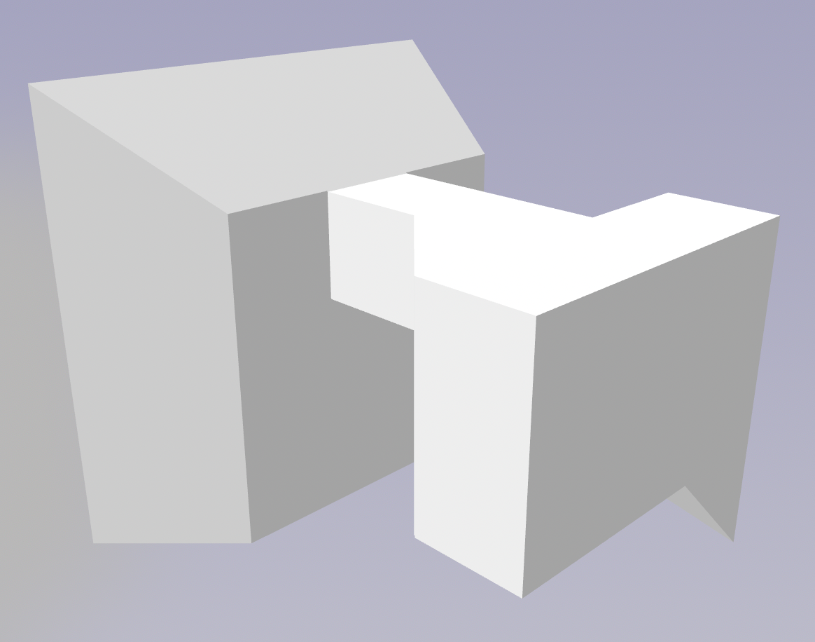
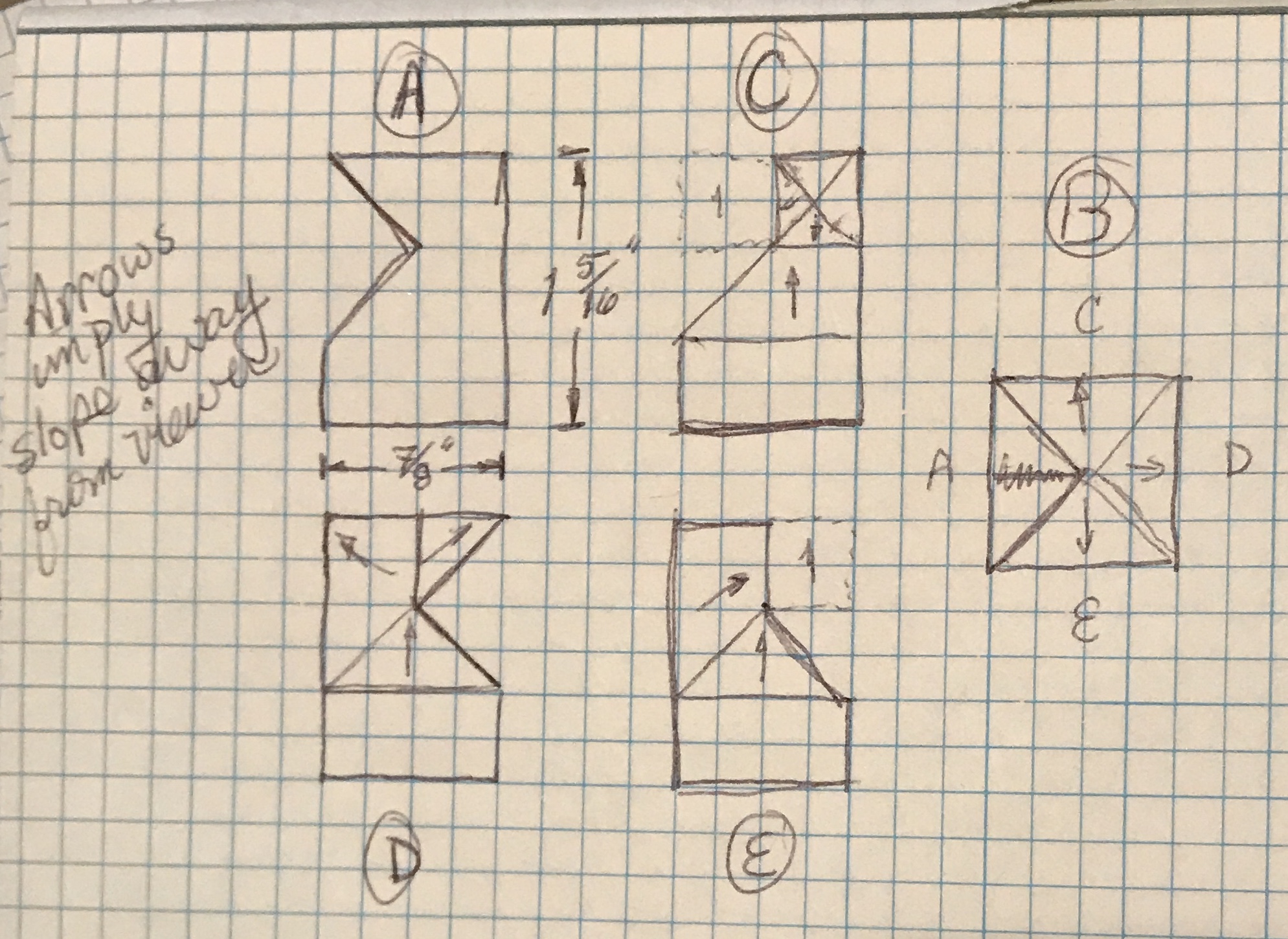
Returning to this puzzle in February, 2021. After studying the pieces for some time this morning I have a good feel for the required shape. The pieces as made have two volumes missing. The first is in front of the triangle post. It is a two-sided hill sloping down and away from the juncture of the triangle post and the slope coming up to meet it. The second is an extension from the top of the triangle post. This is a small two sloped wedge that will fit with the same sloped wedges from the other two pieces and fill a cubic hole that is currently missing. I have sketched out five views of this "new" piece as seen below.
I also decided it was time to jump to a metal version after determining how I might approach cutting each of the angles. Assembling a group of small pieces was considered, but was ultimately rejected. It would be too hard to hold for the final finishing to size cuts. So I am planning to mill most of the piece out of one block. A second part will be made and attached. At this point I also plan to utilize the three outside faces made from oak. So the aluminum central part will need to be attached to the oak when completed.
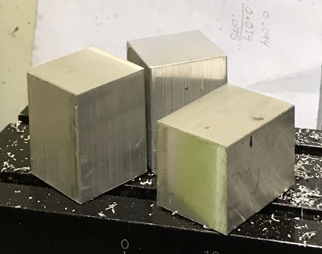
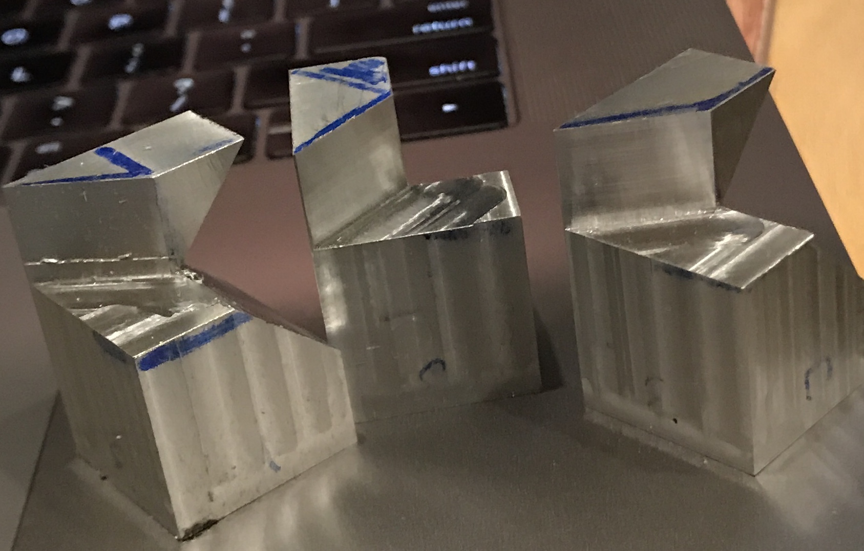
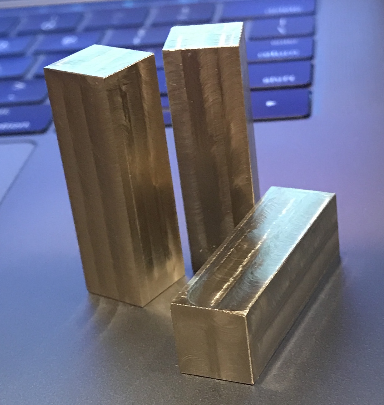
Three 1" X 1" X 1 3/8" lengths of aluminum were cut from a square bar. Each of the pieces was held in the vise with a finished side against a vertical parallel, while one end was faced square and flat with a fly cutter. The pieces were turned over and set on parallels in the vise. The opposite end was then faced to length, 1.31". The three faced parts are shown below.
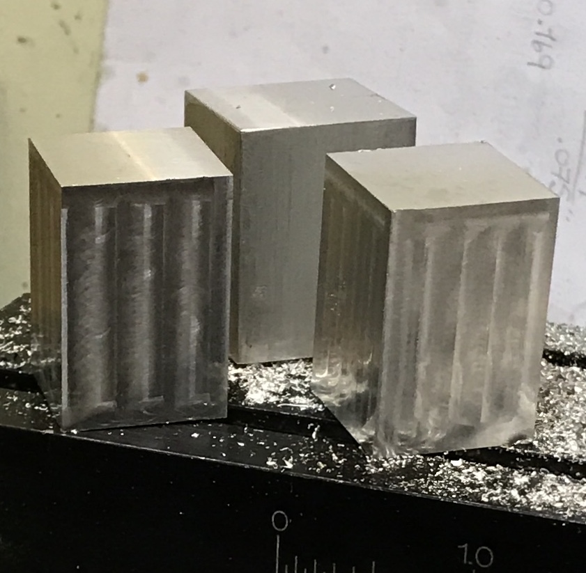
The sides of the blocks were then faced, removing approximately 1/16" from each face. The milling was done with a 5/16" four flute cutter in 0.020" X 0.200 passes. Over a 2 1/2 hour period two of the blocks were milled to 0.875"" X 0.875". These are shown in the picture below.
The third block was reduced to size like the previous two. The faces of the blocks were marked and one end was selected as the bottom. The three blocks were then marked out for the first cut. This cut removed one-half of one end to a depth of 7/16". This cut can be seen in the plan above in sections C & D, labeled 1. The corner was first removed with a hacksaw and then cleaned up to the correct depth, 0.438", in both directions by milling.
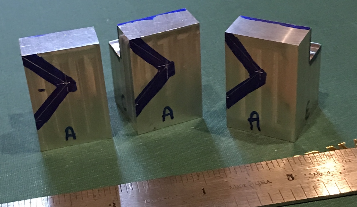
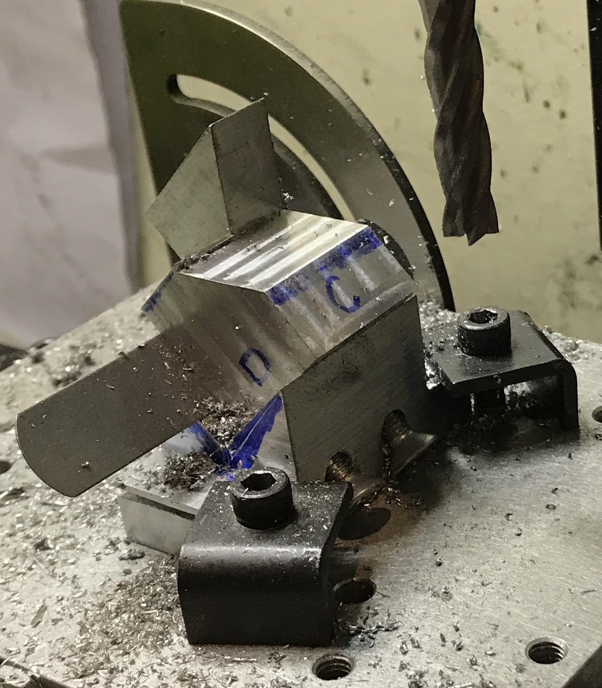
The second cut is a 45° angled cut. This cut runs from the A face to the D face. The point of the angle is 0.438" down from the top and 0.438" in from the side. This point was marked and a line drawn from it to the top left corner on the A face. A point was measured and marked 0.825" down from the top on the left side. A second line was drawn from this new point back to the vertex of the angle. This layout is seen in the first photo below. The hacksaw was again used to remove most of the waste as shown in the second photo below.
A short pause was taken to make an adapter for the dial test indicator. I needed a way to attach it to a shaft in the spindle to set the part at 45°. A 2 1/2" length of 3/8" X 1/2" aluminum was cut off and the ends were milled square. A through hole was drilled 3/16" from one end centered on the 3/8" face with a #21 drill. It was tapped 10-32. A second hole was drilled on the same face, but 3/16" from the opposite end. This hole was drilled through with a #21 drill and then opened for half its depth with a 7/32" drill. The bottom of this hole was also tapped 10-32. The final hole was drilled through the 1/2" face with a 15/64" drill and reamed 1/4". It was located 1/2" from the end and on center. The last task was using the hacksaw to cut through the end of the bar, through the half-tapped hole and to the 1/4" hole. One 10-32 screw was installed to squeeze the 1/4" hole tight around a 1/4" shaft in a mill collet. A second 10-32 screw and washer were used to hold the indicator in place. The picture below shows it in use.
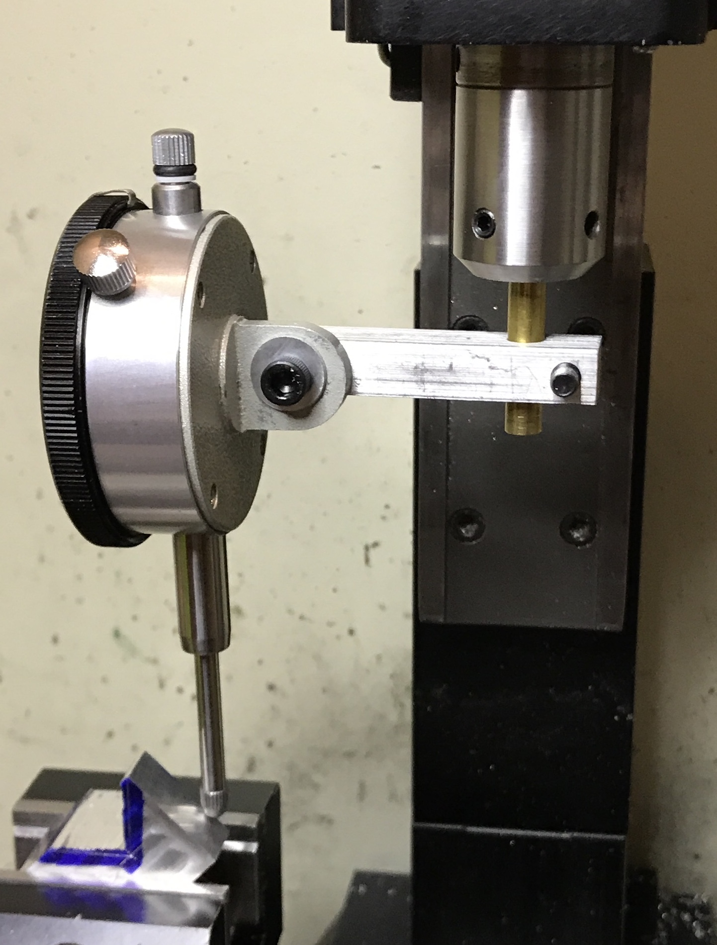
The DTI was put to use and it verified that the angle set by the combination square was accurate. (Later the DTI was used to tram the mill. It was off by 0.004" over about 6" in the X-direction. Removing the paper I had placed over the riser block brought it back within 0.001". It was within 0.001" in the Y-direction as well.) I set the tip of the mill by eye onto the top knife edge of the part. The end mill was lowered 0.015" per pass. Once the end mill reached the saw cut bottom it was moved to the left edge and the bottom was gradually cut over to the vertical wall with 0.020" depth of cut. The end mill was lowered a total of 0.619" and met the inscribed line. The milling was very slow as light cuts were a requirement. Otherwise the part would move in the vise. I am not sure how to hold the part more effectively.
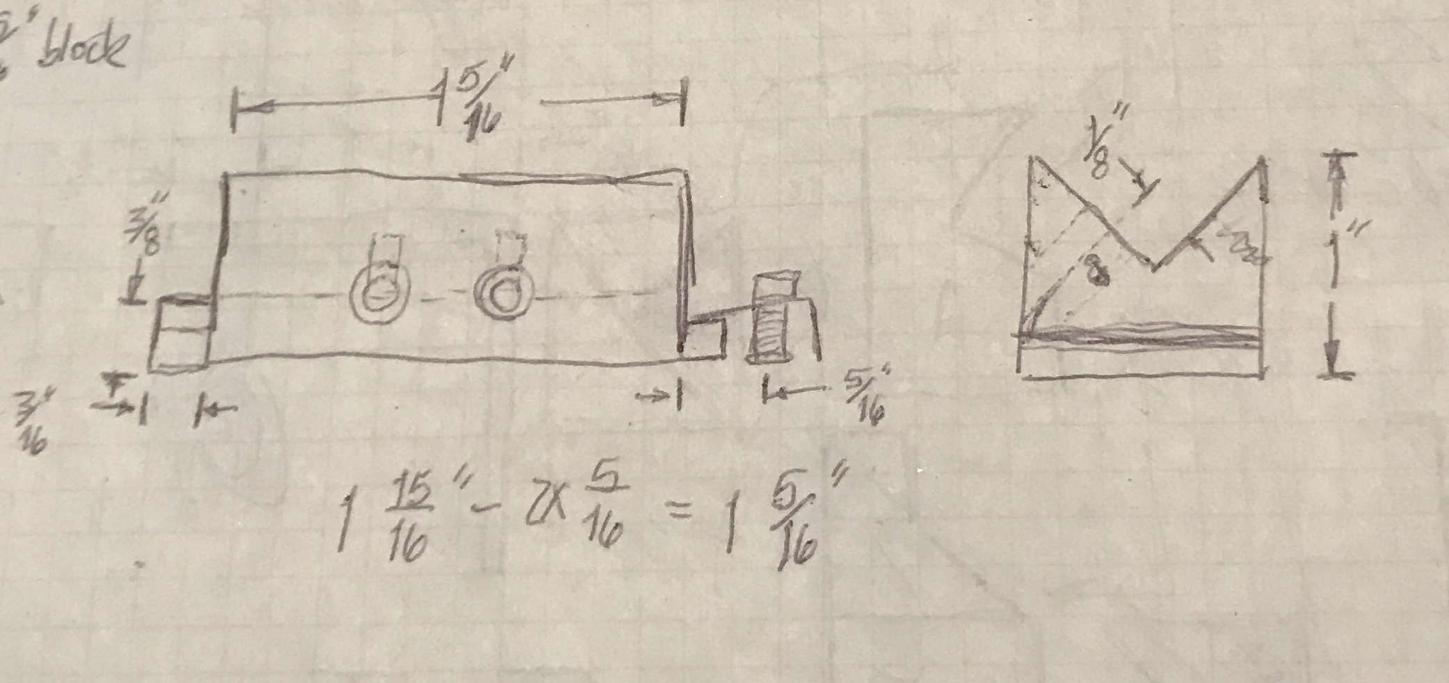
I decided that a custom vee block is needed. It will have holes so the parts can be screwed to the vee block and the block will be clamped to the table or the angle plate as needed. The vee block needs to be clamped securely so it will have clamping pads on the sides. After checking the angle plate it will need to be drilled and tapped for one extra hole. The part will need to be held in two perpendicular orientations for two different cuts. The angle plate is only designed to hold things (vise) in one direction. To fit between two current holes in the angle plate the jig will be a total of 1 15/16" long. The clamping tabs will each be 3/8" high and wide. The clamping tabs are designed to use the same clamps that hold the vise. A picture of the plan is shown below.
A 2" length of 1" square aluminum bar was cut with the band saw. The ends were faced square and to length, 1 15/16". The ends were marked at 3/8" for the tabs. The waste was cut out with a hacksaw and then the parts were milled to the marked lines. The vee was roughly marked on the ends of the bar and it was back to the hacksaw. Clamping the jig was done thoughtfully. First the jig was not evenly clamped top to bottom so a thin piece of cardboard was used. The angle was set with the DTI.
When using the DTI in this fashion it is important that the spindle does not rotate. Any rotation will obscure the result. In this case a bit of folded cardboard was inserted between the pulley and the housing. This was sufficient to keep the spindle fixed when the DTI was used. Additionally, the DTI spindle is raised during table movement and then set back down against the object measured.
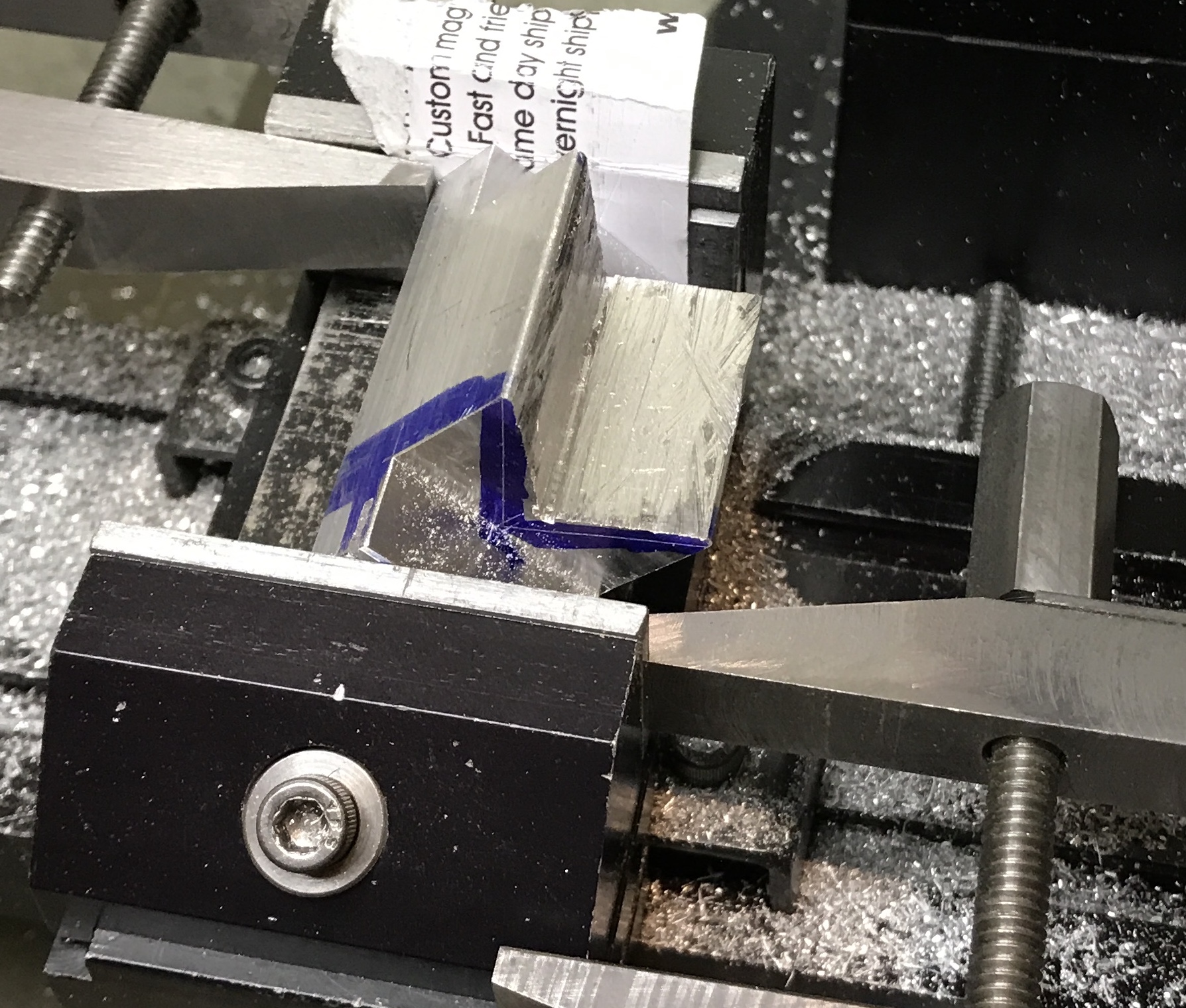
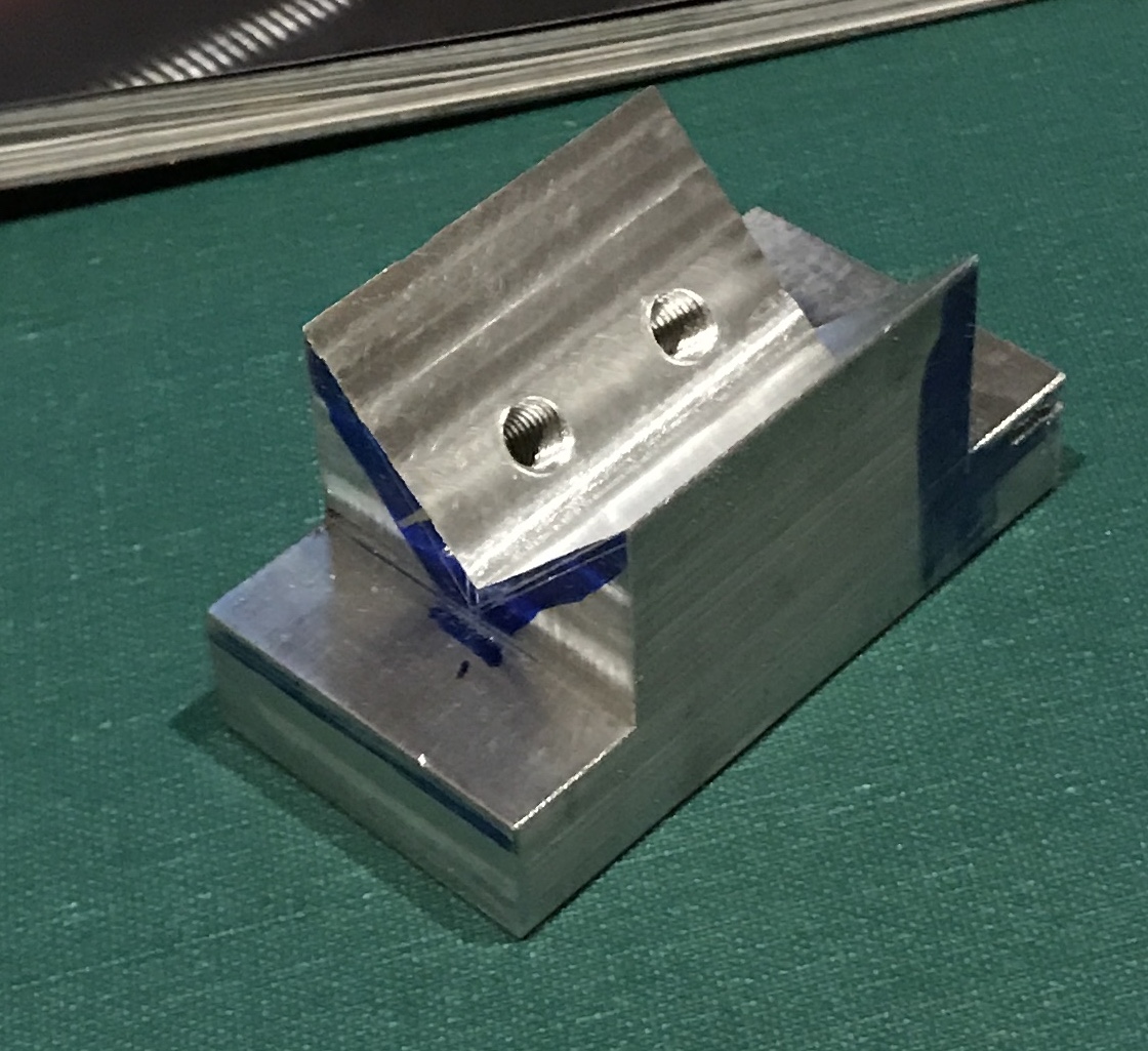
Two machinist's clamps were used as stops to keep the jig from rotating during the cuts. With the jig clamped the vertical face was cut in 0.25" sections in 0.005-0.010" deep passes. Then the horizontal surface was cut in 0.020" passes. After completing the vee groove two holes were drilled. The holes were drilled 0.23" from the bottom of the vee, 1/2" apart and 5/32" in from the sides. They were drilled with a center drill followed by a #21 drill and then tapped 10-32. The clamped jig is shown in the first shot below and the finished jig in the second.
To transfer holes to the parts is not as simple as I had first thought. I cannot use the jig as a drill guide. It is too difficult to hold it at the proper angle. Also the holes that have been tapped eventually need to be through holes. However, I can make temporary use of the threads. A 10-32 screw was held in the lathe and its end was cut to a point. It was screwed into one hole with a part clamped in place. It left a decent divot. This part was clamped in the vise against a vertical parallel as a stop. It was center drilled, drilled with a #21 drill, and tapped 10-32. This was repeated on the other two parts. The table was moved 0.50" and the second holes were drilled and tapped as well.
Completion of the jig and putting the screw holes in the parts allowed me to finish cutting the two parts similarly to the first, but with much better rigidity. The setup for these cuts is shown in the photo below. When the screws were tightened, the part was not pressed against the back of the vee. Using a set of thickness gauges it was discovered that the gap was 0.016". So the parts were clamped with this gauge in place. Aligning the jig with the angle plate is not simple. I will need to find a better way to do this. Milling went better with a shot of WD-40.
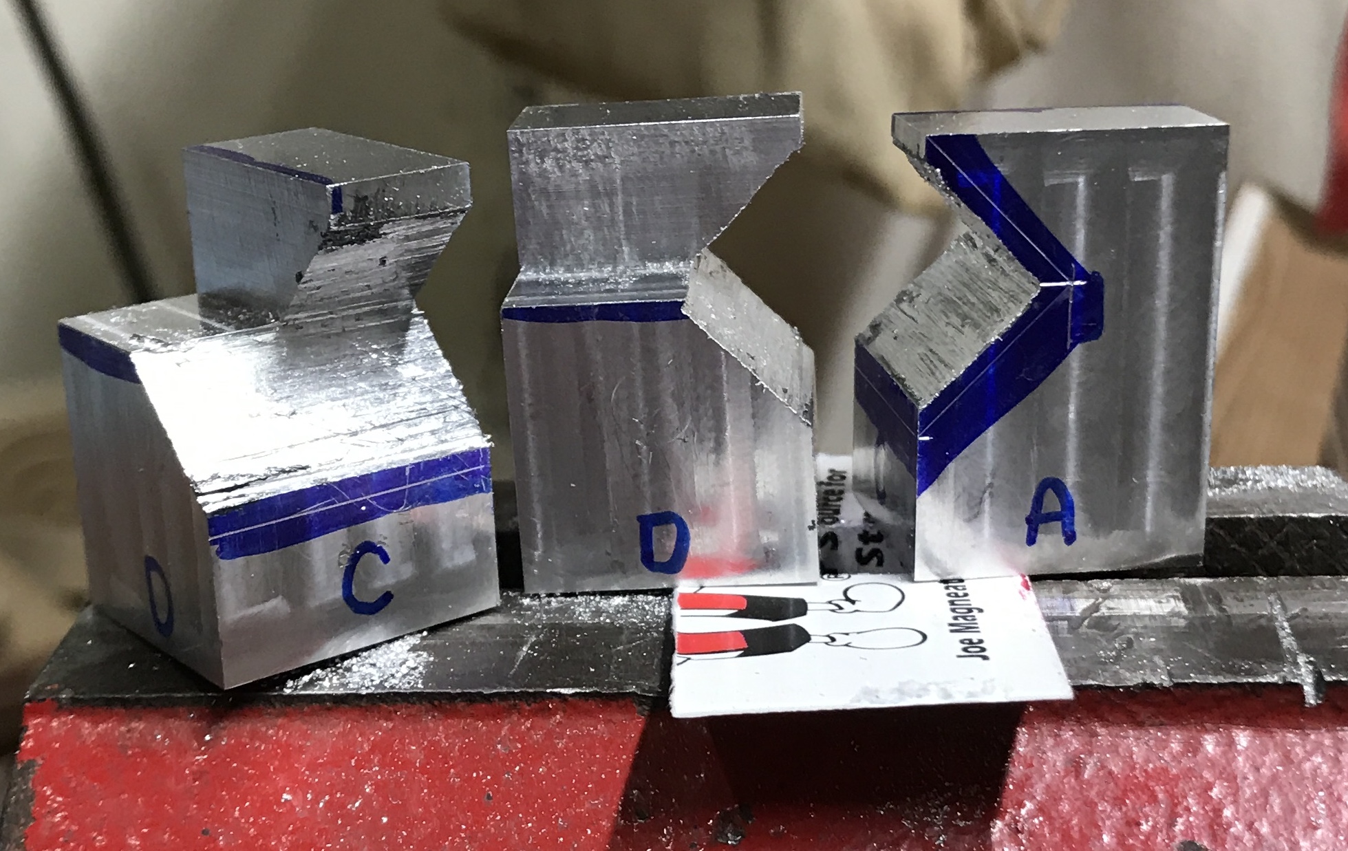
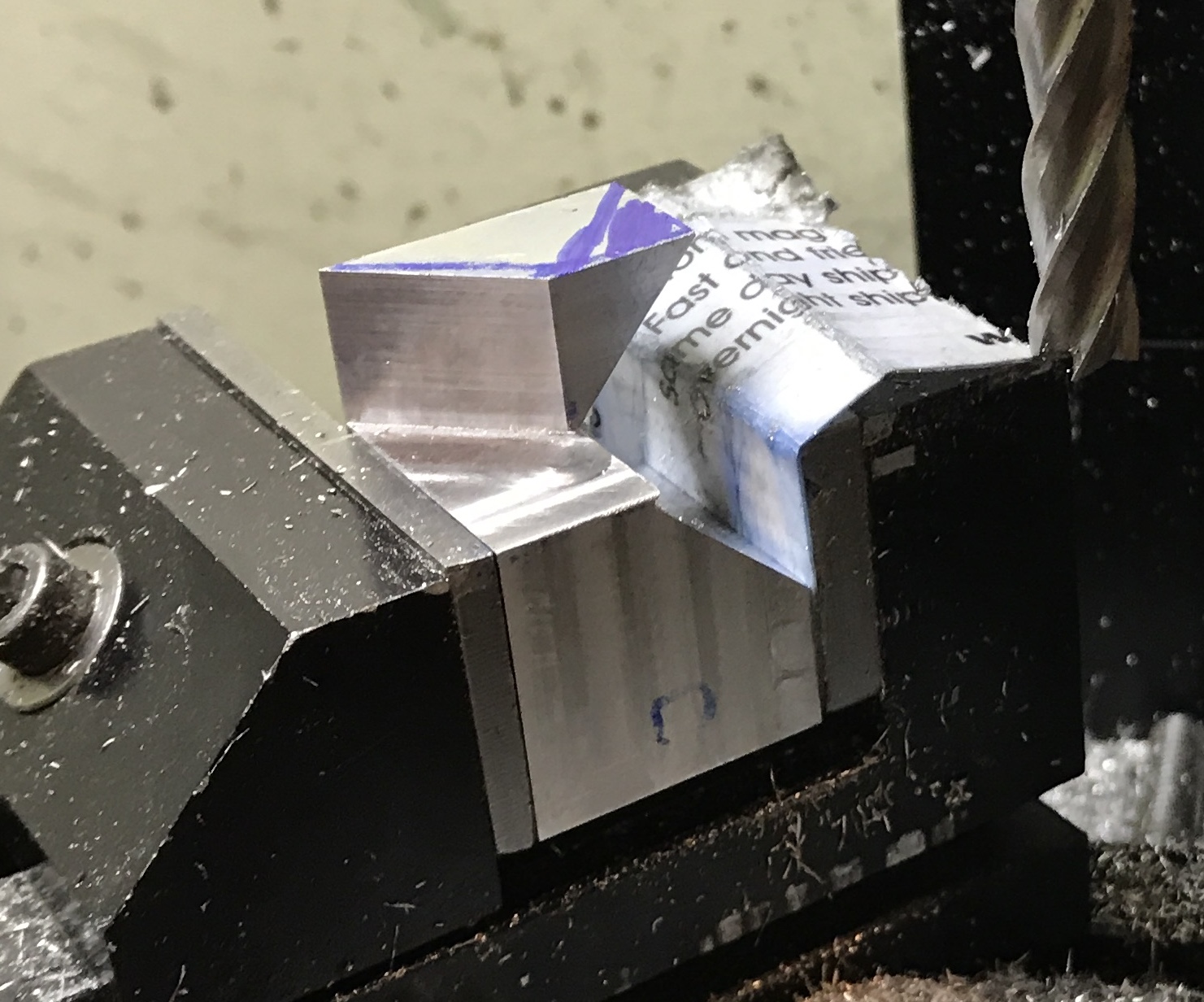
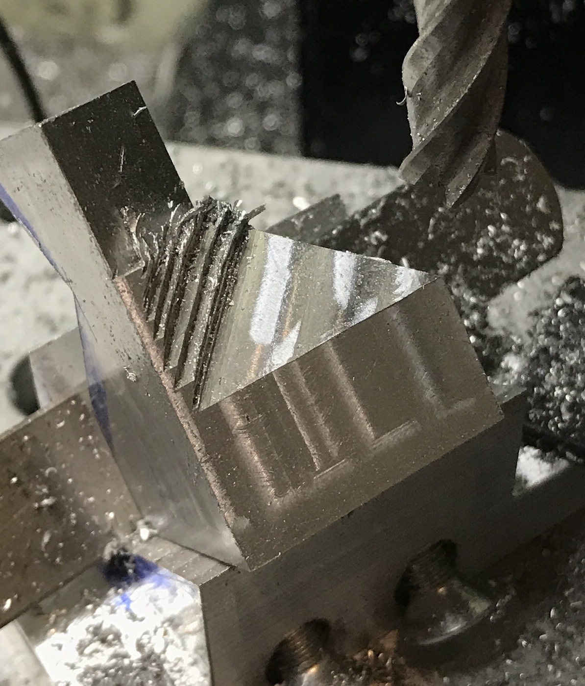
After studying the problem for some time I believe I have figured out how to make the four remaining cuts. Only two require the use of the jig. The first cut that needs to be made is to cut off the corner of the tower. The foremost corner shown in the photo below needs to be cut off straight down to the plane to its right. The vise will be turned 45° for this cut. The second cut on the tower is also made with the vise at a 45° angle. Clamping from the A to D faces aligns the three points defining the plane of this cut. This can also be imagined from the photo below.
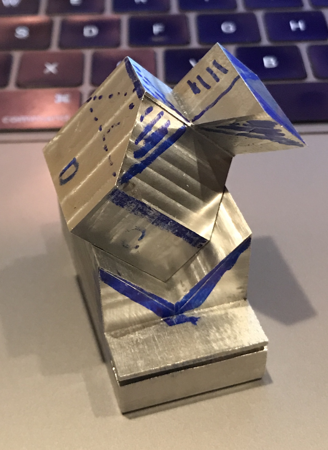
There are no compound cuts needed to finish!. The jig is needed and requires a slight modification for the fourth cut. With the part set in the jig as shown in the photo below the three points that define the cutting plane for the third cut are all at the same level. These points are the frontmost corner, the juncture of the three planes (center), and the juncture of the two dotted lines in the back. Clamping for this cut uses one of the two holes drilled in the bottom on the A side. Since the E side is down a second hole has to be added.
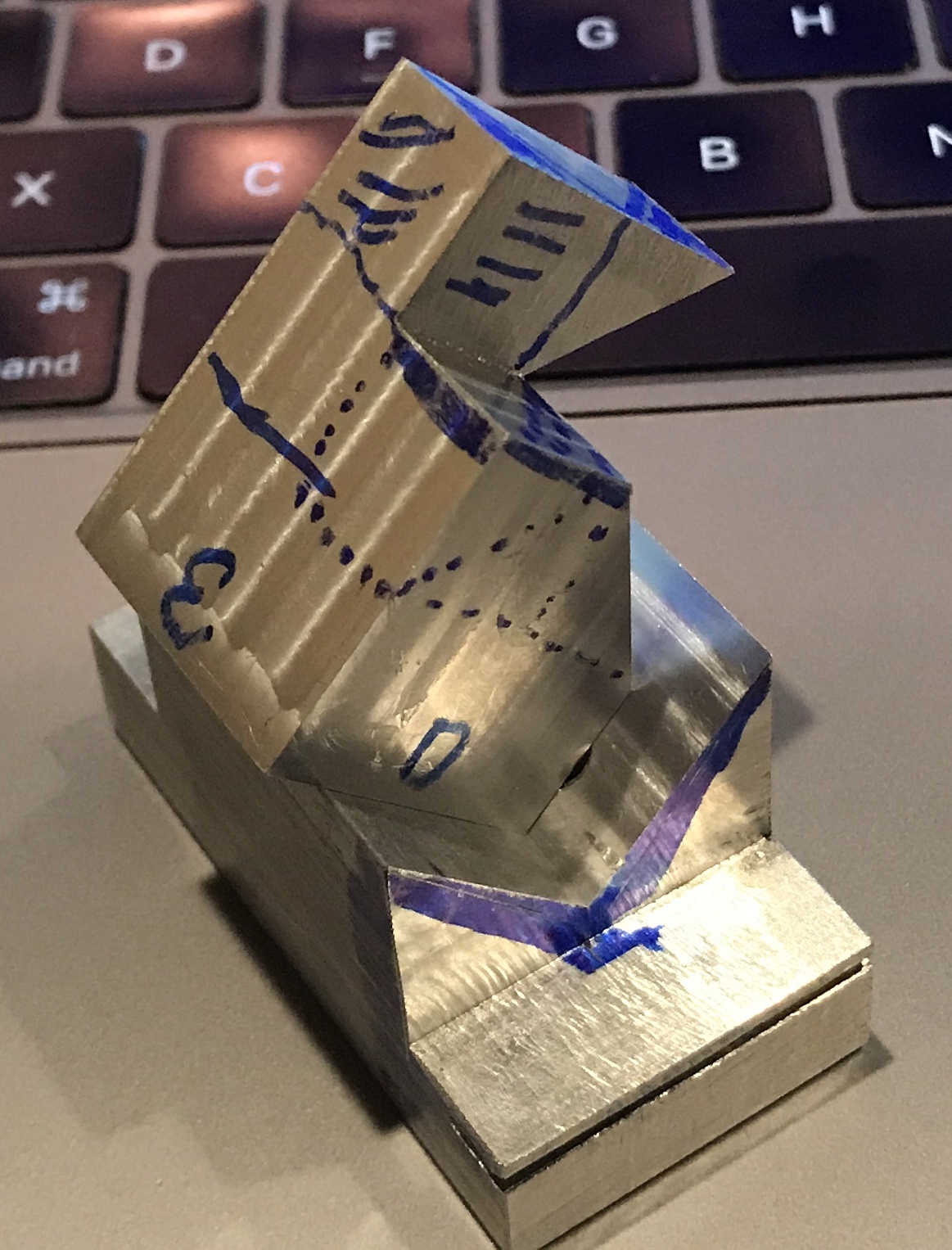
The final cut is also a central cut, just the opposite side of the part from the cut outlined above. The proper alignment for this cut is shown in the next photo. The three points defining this cutting plane are the foremost juncture of three dotted lines, the juncture of three planes at the back of the blued area, and the point where the solid line meets the back. The first two points are shared by these last two cutting planes. This setup in the jig also reuses one hole in the jig and requires a new hole on the C edge of the bottom face. The jig will need to be turned 45° to avoid milling the column face that is implied by the two hatched faces in the picture below.
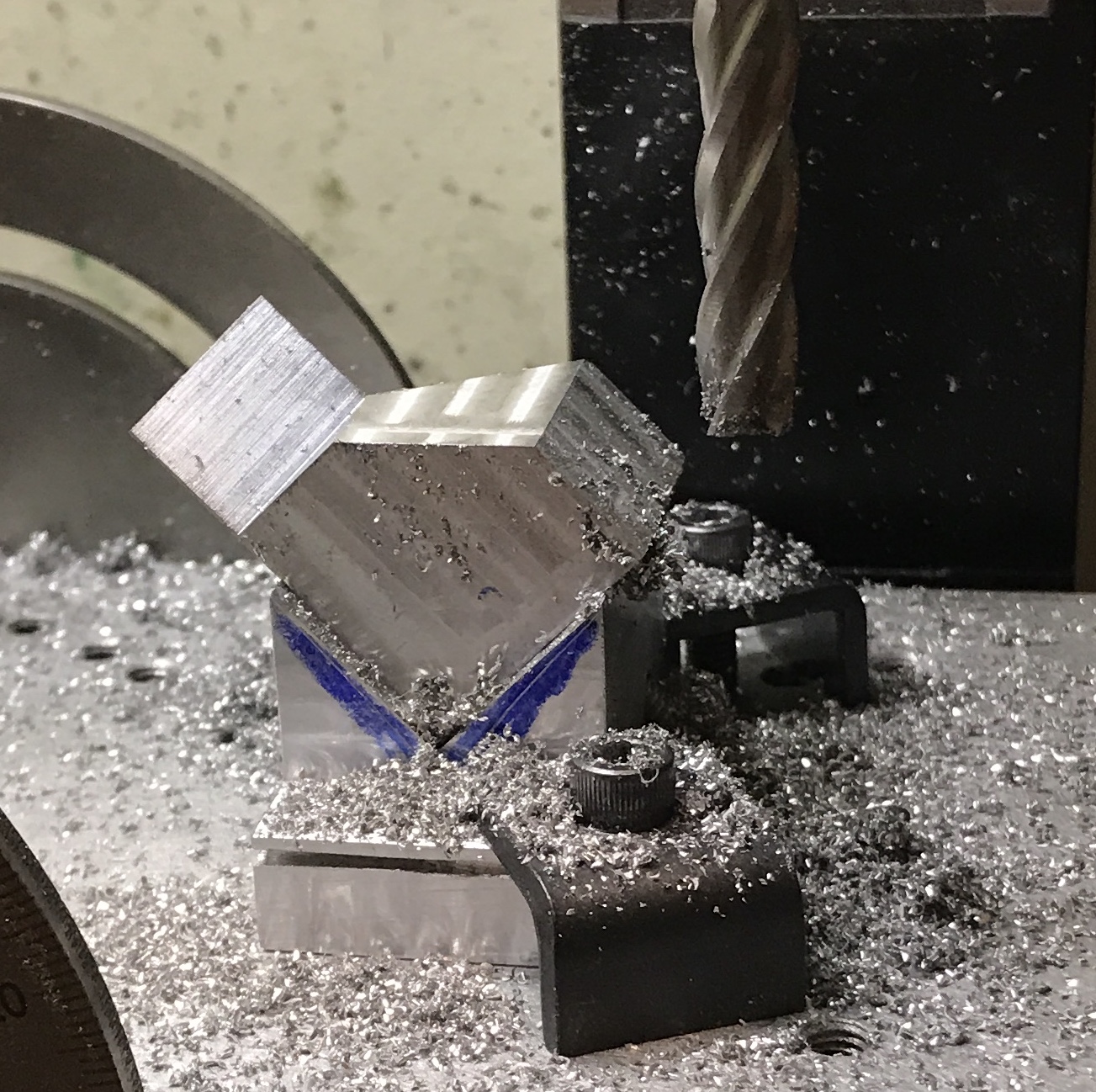
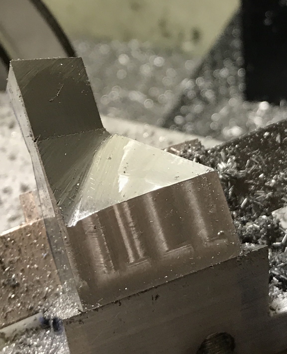
The first of the remaining four cuts was tackled this morning. Each part was marked with a Sharpie and then roughly cut with a hacksaw. The vise was set at 45° for these cuts. The mill vise was then set at 45° with a combination square. Each part was clamped, the z-axis was set to zero with the end mill touching the top, the vertical face was milled, and then the horizontal face was milled to a depth of 0.438". Again the WD-40 was helpful on the 0.020" deep horizontal face cuts. The picture below shows these cuts completed.
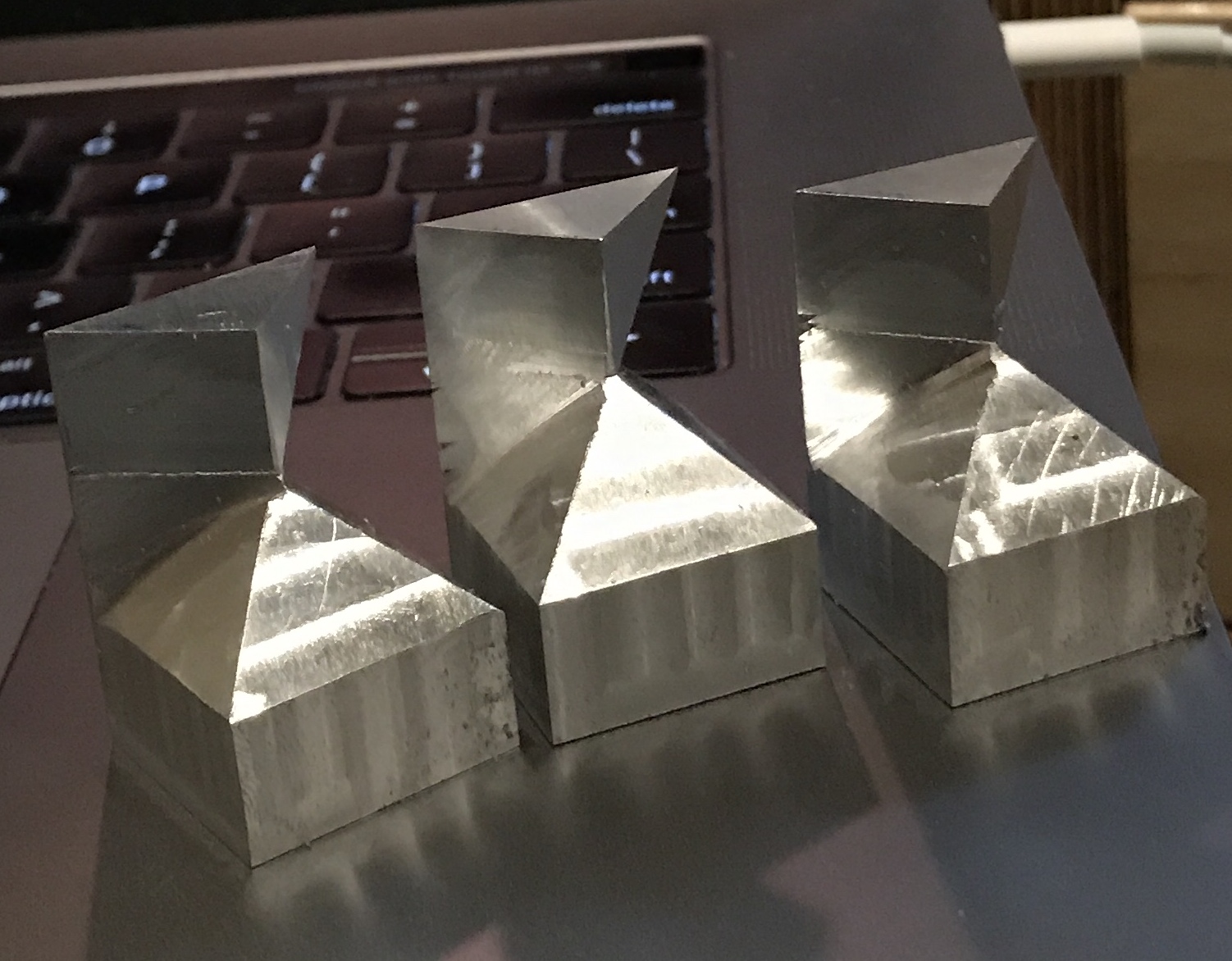
The next cut is also on this top column. It can be seen in the photo above, where the central part is marked on the back of the top side. It is 90° from the first cut. It proceeded just as the cut above with clamping in the vise still set at 45°, but without the removing any waste with the hacksaw. All three parts were cut quickly. The first picture below shows the setup and the second, three completed cuts.
A second hole was drilled on the E side of the bottom. When setting the part in the jig for the third cut the E side is on the hole side of the vee. One hole had a screw installed and the other hole was punched. This punch mark was center drilled, drilled #21, and tapped 10-32. This was repeated for the other two parts. A part was installed in the jig and the jig was attached to the angle plate. The plate was squared to the table and the jig was squared to the plate. The end mill was touched off on top of the section to be cut and 0.020" cuts were made with WD-40 as lubricant. The milling was stopped when the surface reached the inside corner. The setup can be seen in the first photo below. The second photo shows the three parts with the third cut complete.
The part was returned to the jig but with a new face on the hole side. As before one hole aligned and had a screw installed. The other hole was transferred to the part with a 7/32" transfer punch. This punch mark was center drilled and tapped as above. As soon as the first part was placed in the jig and on the angle plate a new challenge was discovered. Cutting past the tower is not simple as the previous cut. The tower angles away from the cut in two directions. So the cut was made in steps away from the tower as the end mill dropped lower. The first picture below shows the roughly cut first part and the second shows the filed part. The last two show the three completed parts: the separated parts and the parts put together. This last photo indicates that the parts need a little more material removed in order to fit well.
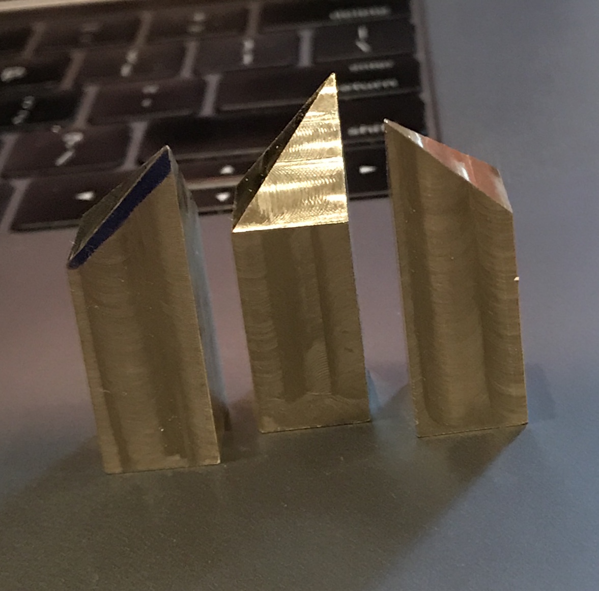
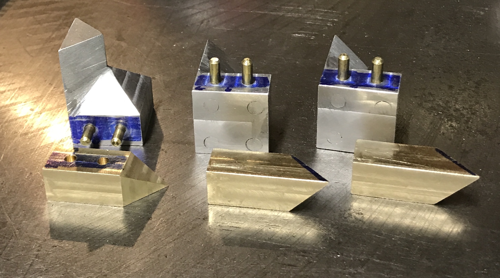
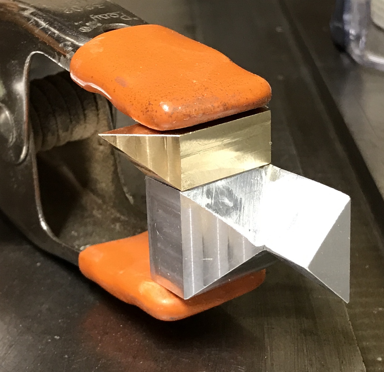
The next part to make is the part that sits along the bottom of the E side. This part is 1 5/16" long with a 7/16" square cross section. It comes to a point in one corner. This is most easily seen in the ninth picture from the top. I found a length of 1/2" X 1" brass bar in the garage. A 3" length was cut off. This length was cut into two 1 1/2" lengths and each of these was sawed down the middle. Three of these four bars were cut to size as shown below. The ends of the parts were cut off at a 45° angle with a hacksaw. Then the spindle was set at 45° with the combination square. The parts were milled first on the roughly cut side, turned 90° and milled on the adjacent side. The resulting three parts are shown in the second photo below. I need to decide on the most appropriate way to attach them to the first parts, so they look like the third photo below.
Some cleanup activity was required on the aluminum parts. Some time was spent sanding the last cut. It is difficult to get it flush with the upper part of the column. I decided to plug all of the holes in the bottom that were required for jig use. I made 12 small threaded rods from aluminum. A 1/4" rod was chucked with about 5/8" protruding from the chuck. It was faced and reduced to 0.190" for about 1/2". The end was chamfered with a file. It was threaded 10-32 with the tailstock die holder. About 5/16" of this was parted off. WD-40 was important for all of the steps. The process was repeated 11 times. The photo shows the screws in their respective holes.
The screws were removed from the twelve holes and a drop of Loctite 538 was added to the hole. The screws were installed and tightened with a pair of needle nose pliers. The glue was allowed to dry for about 24 hours. The protruding screws were sanded off on the belt sander leaving about 1/16". I don't trust my skills with this machine to go any farther. The remainder was removed with the two flute cutter in 0.005" increments. The photo shows the acceptable result. It probably would have been better to use studs.
The plan for joining the aluminum and brass parts is with two 1/2" long studs. Six 1/2" lengths of 1/8" (0.1255") brass rod were cut with a hacksaw. The rods were within 0.010" of 0.500" except for two that needed 1/32" removed. The ends were all chamfered in the lathe. The parts were located with an edge finder. Holes were drilled 1/4" (and 5/8") from the back end and 7/32" from the bottom to a depth of 0.265". The holes were reamed to 0.125". The photo below shows all of the parts completed and ready for assembly. Decided that I didn't want both parts to be a press fit so the holes in the brass were opened up to 0.128 with a #30 drill.
The pins were pressed into the aluminum parts in a vise using the brass parts as guides. Epoxy was made up and a small amount was placed in the holes in the brass and on its mating surface. The parts were pressed together with a pinch clamp. The aluminum parts with the pins pressed in and the clamped parts are shown below. The epoxy takes at least 24 hours to harden, maybe more in the cold basement.
After allowing the epoxy to harden it was on to the next step. I only had two of the original three wooden parts. A 1/2" thick piece of oak was cut to 1.75" X 1.75" on the table saw. First, the thickness of the block was reduced to 0.439" in the mill with the two flute cutter. Then the milling head was tilted to 45° and the two adjacent edges were mitered with the same cutter. Carpet tape was cut to attach the wooden part to the top of the aluminum column. The pictures below show this part of the story.
Do the parts still go together after my modifications to the plans? They do not seem to want to slide together. It may be that the puzzle only works if the cube is not completely full. It may require gaps so the pieces will slide together. Thus it is not a true dissection puzzle. It is not clear which modification has resulted in an obstruction. There is also a slim possibility that insufficient clearance is the culprit.
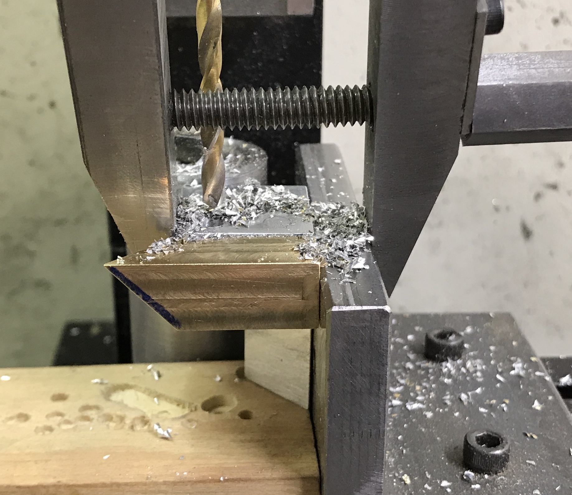
Decided to leave things as they are and complete a cubic dissection, even if it is no longer a puzzle. So all that remains is attaching the wood and finishing it. The angle plate was set up on the mill along with a cylindrical parallel. A block of waste wood was set in this corner. The wood was approximately marked for the two holes. The drill was aligned with one and the hole was drilled through with a 7/32" drill. This was repeated on the other two wooden parts. The drill was changed to a #21 drill and the aluminum part was clamped in place with a machinist's clamp. It was drilled 0.40" deep. The other aluminum parts were drilled the same way. The wooden part was returned to this same setup and the hole was countersunk with a 7/16" drill approximately 3/16" deep. Again this was repeated on the other two parts. The holes in the aluminum were tapped 10-32. Six screws were cut to size. The other holes were drilled similarly but closer to the opposite corner. The first photo shows the drilling setup and the second shows the three joined pieces.
After disassembly the wood was sanded, stained and varnished. The three parts were assembled. The two pictures below show the final result.